


10 MDrivePlus CANopen R020507
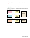
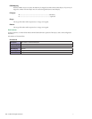
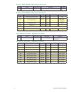
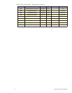
PDO Mapping
The MDrivePlus CANopen allows you to map objects to PDOs to reduce the transfer application data more efficiently. By
using the PDO the user can map a PDO to multiple objects (8 Data Bytes max.)
The example will show RPDO 1400
h
mapped to Control Word (6040
h
) and Target Position (607A
h
).
RPDO Index Sub-Index Mapped To Index Bytes
1600
h
00
h
1600
h
01
h
6040
h
2
1600
h
02
h
607A
h
4
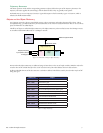
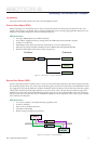
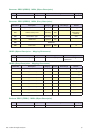
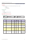
PDO Mapping Procedure (Consumer PDO)
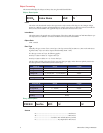
PDO Mapping Example 1: Profile Position Mode – Mapping ControlWord and Target Position to RPDO1
Step Action Index Sub-Index Bytes Value
1
Place MDrive in PreOperational State —
2 Turn Off RPDO1 1400
h
01 — 8000 01C0
h
3
Set 1600
h
Sub-Index 00 to 0 1600
h
00 — 0
h
4 Map ControlWord 6040
h
to 1600.01
h
, Establish New
Set Point
6040
h
00 2 005F
h
5
Map target_position 607A
h
to 1600.02
h
607A
h
4
Desired Axis
Position in Hex
6 Set 1600
h
.00 to 2 Max Sub-Indexes 1600
h
00 — 2
h
7 Turn On RPDO1 1400
h
00 — 0000 01C0
h
8 Place MDrive in Profile Position Mode 6060
h
00 1 1
h
9 Place MDrive in Operational State
10 Send PDO to MDrive
Note: Before re-sending the PDO to the MDrive, the old set-point must be cleared by sending 6040.00
h
004F
h
in a
second PDO or in an SDO.
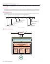
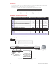
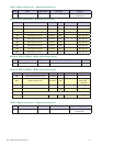
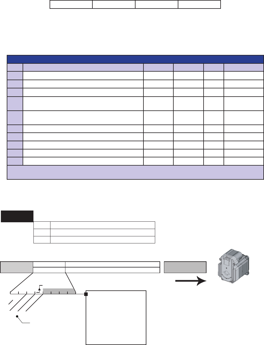
MDrive CANopen
Node
1601h
0 = 2 (# of SubIndex Entries
1 = 2 Byte ControlWord (6040h)
2 = 4 Byte Commanded SetPoint (607A)
RPDO 2
BYTES 0 - 1
BYTES 2 - 5 BYTE 6 - 7
ControlWord
003F
h
Set-Point (Position) Data
Unused
110 1 1 1
F = Operation
Enabled
abs/rel
change set immed.
new set-point
Default Mapping Example - Consumer PDO 2
00 00 00 00
Index
SubIndex
ControlWord = 03F
h
Move to Absolute SetPoint
ControlWord = 05F
h
Move to Relative SetPoint
ControlWord = 00F
h
Reset New Set-Point Bit
to Prepare for Next Move
Transition Bit
MUST be reset to zero
between set-points
Figure 2.3: PDO Mapping Showing the Default Mapping for RPDO2