


8
C H A P T E R 1 Intel Express 550T Routing Switch
8
• Customer-supplied screws for securing the switch in the rack.
Mounting screws are not provided because the required sizes
may vary from rack to rack.
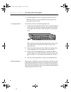
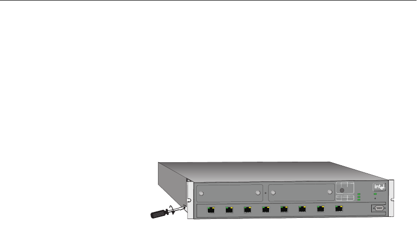
In an equipment rack To mount the switch in a standard equipment rack:
1 Attach the mounting bracket marked “Left” to the left-hand side
of the switch, and attach the mounting bracket marked “Right”
to the right-hand side of the switch, using the four screws pro-
vided.
Make sure that you attach the mounting brackets to the correct
sides. Otherwise the switch will not align correctly in the
equipment rack.
2 If the four rubber feet prevent the switch from standing firmly
on the equipment rack’s side support rails, remove them.
3 Set the switch in the equipment rack, and make sure there is
adequate space for air flow around the switch (see “Allow ade-
quate ventilation” in “Positioning and Installing the Switch”, p.
7).
4 Screw the mounting brackets securely to the equipment rack.
Ambient temperature If the switch is installed in a closed or multi-rack assembly, the oper-
ating ambient temperature of the rack environment may be greater
than the ambient temperature of the room. Make sure that the temper-
ature of the rack environment does not exceed the recommended op-
erating temperature for the switch.
971126 Awaiting Drawing from EBZ
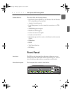
1679
Power
Intel Express
550T Routing
Switch
Status
Temperature
RPS
1
2
3
8
7
6
5
4
Reset
Console
9600-8-N-1
Slot B
Slot A
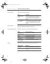
Blink
Solid
Solid
Off
Activity
Link
100 Mbps
10 Mbps
Collision
Disabled
Full duplex
Half duplex
LEDs
LEDs
Green
Green
Orange
Orange
Port Status
500.book Page 8 Thursday, September 2, 1999 1:50 PM