


ADE-9040 User’s Manual
17 / 55
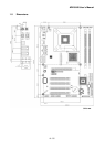
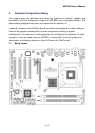
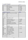
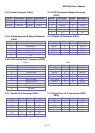
2.3 Jumpers/Connectors Setting
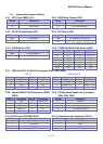
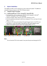
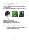
2.3.1 RTC Clear CMOS (JP1) 2.3.2 BIOS Write Protect (JP2)
PIN No. Description
1-2 Normal operation
2-3 Clear CMOS
PIN No. Description
1-2 BIOS write disabled
2-3 BIOS write enabled
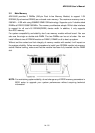
2.3.3 AT/ATX Power Select (JP3) 2.3.4 DVI Select (JP4)
PIN No. Description
Open ATX Power
1-2 AT Power
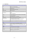
Item. Description
Open PCI Express x16 Display
DVI
1-2, 3-4, 5-6, 7-8,9-10,11-12, 13-14,
15-16, 17-18, 19-20,21-22,23-24 short
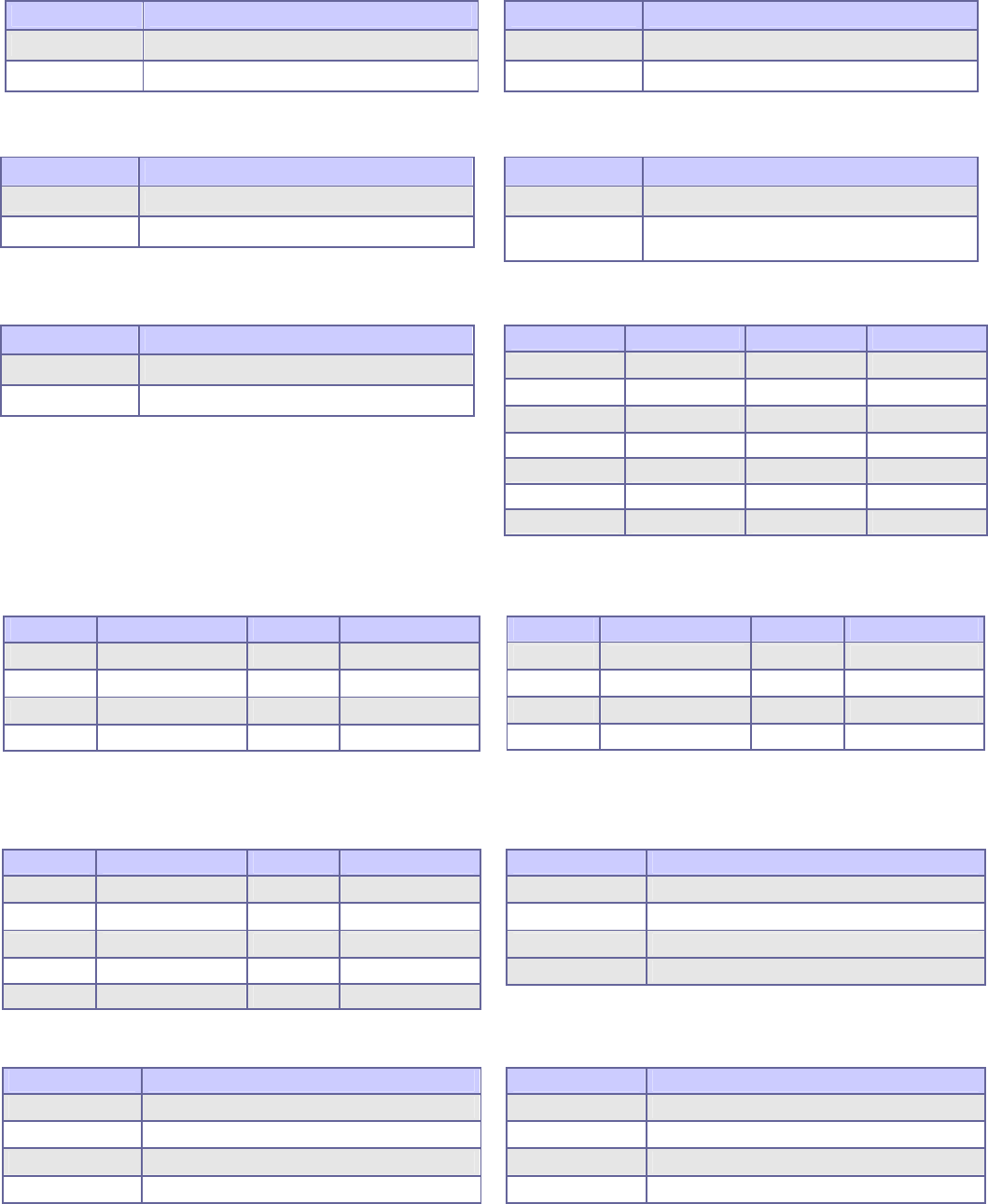
2.3.5 P-ATA Select (JP5) 2.3.6 COM2 RS-232/422/485 Select (JPB1)
PIN No. Description
Open P-ATA enabled
1-2 P-ATA disabled
PIN No. RS-232 RS-422 RS-485
1-2 OFF ON (Term.) ON (Term.)
3-4 OFF ON (Term.) ON (Term.)
5-6 OFF OFF ON
7-8 OFF ON OFF
9-10 OFF ON ON
11-12 ON OFF OFF
13-14 OFF OFF ON
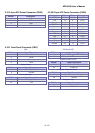
2.3.7 USB 2/3/4/5/0/1 & LAN1/2 Connectors (CN1, CN2, CN22)
LAN 1/2
PIN No. Description PIN No. Description
1 TX+ 5 NC
2 TX- 6 RX-
3 RX+ 7 NC
4 NC 8 NC
USB 0/1/2/3/4/5
PIN No. Description PIN No. Description
1 +5 V (fused) 5 +5 V (fused)
2 USBP0-/2-/4- 6 USBP1-/3-/5-
3 USBP0+/2+/4- 7 USBP1+/3+/5+
4 Ground 8 Ground
2.3.8 Internal USB 6/7/8/9 Connectors (CN23,
CN24)
2.3.9 CPU/System/Chassis Fan Connector
(CN4, CN5, CN6)
PIN No. Description PIN No. Description
1 +5V 6 USBP7+/9+
2 +5V 7 Ground
3 USBP6-/8- 8 Ground
4 USBP7-/9- 9 NC
5 USBP6+/8+ 10 NC
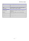
PIN No. Description
1 Ground
2 +12V
3 Fan Status Signal
4 Fan Speed Control
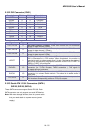
2.3.10 CD-In from CD-ROM (CN13) 2.3.11 Extend Line-out Connector (CN14)
PIN No. Description
1 CD-L
2 CD-Ground
3 CD-Ground
4 CD-R
PIN No. Description
1 LINE_OUT_L
2 GND
3 GND
4 LINE_OUT_R