


ADE-9040 User’s Manual
19 / 55
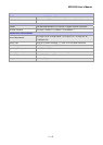
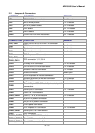
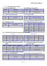
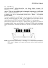
2.3.19 4-pin ATX Power Connector (CN25) 2.3.20 24-pin ATX Power Connector (CN26)
PIN No. Description
1 GND
2 GND
3 +12V
4 +12V
Description PIN No. PIN No. Description
+3.3V 13 1 +3.3V
-12V 14 2 +3.3V
Ground 15 3 Ground
PS_ON 16 4 +5V
Ground 17 5 Ground
Ground 18 6 +5V
Ground 19 7 Ground
-5V 20 8 PW_OK
+5V 21 9 5VSB
+5V 22 10 +12V
+5V 23 11 +12V
Ground 24 12 +3.3V
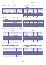
2.3.21 Front Panel Connector (CN27)
IrDA
PIN No. Signal Description
1 +5V
5 IRRX
7 Ground
9 IRTX
System Reset
PIN No. Signal Description
2 Reset
4 Ground
External Speaker
PIN No. Signal Description
8 Speaker
14 +5V
IDE Active LED
PIN No. Signal Description
13 +5V (Pull-up for HDD LED)
15 HDD active# (LED cathode terminal)
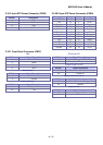
System Power On LED
PIN No. Signal Description
18 +5V
22 Power On
System Power On Switch
PIN No. Signal Description
23 Power button control signal
25 Ground
Keyboard Lock
PIN No. Signal Description
24 Keyboard lock
26 Ground