


Intel®
Compute Module MFS2600KI TPS Product Overview
Revision 1.0 3
Intel order number: G51989-002
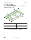
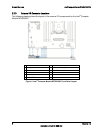
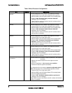
2.2 Compute Module Layout
2.2.1 Connector and Component Locations
The following figure shows the board layout of the Intel
®
Compute Module MFS2600KI. Each
connector and major component is identified by a number or letter. A description of each
identified item is provided below the figure.
A
CPU 1 DIMM Slots
I
CPU 1 Socket
B
CPU 2 DIMM Slots
J
Power/Fault LEDs
C
Mezzanine Card Connector 1
K
Power Button
D
Mezzanine Card Connector 2
L
Battery
E
Midplane Power Connector
M
Activity and ID LEDs
F
Midplane Signal Connector
N
Video Connector
G
Midplane Guide Pin Receptacle
O
USB Ports 2 and 3
H
CPU 2 Socket
P
USB1 Ports 0 and 1
Figure 1. Component and Connector Location Diagram