


Intel
®
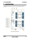
Compute Module MFS2600KI TPS Connector/Header Locations and Pin-outs
Revision 1.0 35
Intel order number: G51989-002
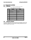
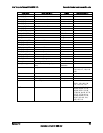
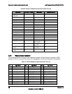
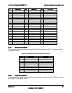
Signal Name
Signal Description
Purpose
Connector Location
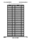
PCIe_1_C_TXN
PCIe TX- of Lane C Link 1
Host connect
84
PCIe_1_C_RXP
PCIe RX+ of Lane C Link 1
Host connect
85
PCIe_1_C_RXN
PCIe RX- of Lane C Link 1
Host connect
87
PCIe_1_D_TXP
PCIe TX+ of Lane D Link 1
Host connect
90
PCIe_1_D_TXN
PCIe TX- of Lane D Link 1
Host connect
92
PCIe_1_D_RXP
PCIe RX+ of Lane D Link 1
Host connect
93
PCIe_1_D_RXN
PCIe RX- of Lane D Link 1
Host connect
95
Clk0_100M_PCIe_P
100MHz clk +
PCIe Clk
101
Clk0_100M_PCIe_N
100MHz clk -
PCIe Clk
103
SMB_SCL
SMBus* Clock
Mngt connect
18
SMB_SDA
SMBus* Data
Mngt connect
17
HSC_0_LNK_LED
HSC 0 Link LED driver
LED control
19
HSC_1_LNK_LED
HSC 1 Link LED driver
LED control
21
HSC_2_LNK_LED
HSC 2 Link LED driver
LED control
23
HSC_3_LNK_LED
HSC 3 Link LED driver
LED control
25
HSC_0_ACT_LED
HSC 0 Activity LED driver
LED control
20
HSC_1_ACT_LED
HSC 1 Activity LED driver
LED control
22
HSC_2_ACT_LED
HSC 2 Activity LED driver
LED control
24
HSC_3_ACT_LED
HSC 3 Activity LED driver
LED control
26
WAKE_N
PCIe WAKE_N signal
Wake on LAN
28
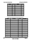
Reset_N
Reset signal (Active Low)
Mezz Reset
100
Mezz_PRES_N
Mezzanine Present signal (active
Low)
Present
indication
98
P12V
12V power
Power
115, 116, 117, 118, 119,
120
P3V3
3.3V Power
power
5, 6, 7, 8, 9, 10
P5V
5V power
power
1, 2
P3V3AUX
Auxiliary power
Aux power
13, 14, 15, 16
Rsvd
Reserved pins
Future use
29, 31, 106, 108, 109,
111, 112, 113, 114
GND
Ground
3, 4, 11, 12, 27, 30, 32,
33, 35, 38, 40, 41, 43,
46, 48, 49, 51, 54, 56,
57,59, 62, 64, 65, 67, 70,
72, 73, 75, 78, 80, 81,
83, 86, 88, 89, 91, 94,
96, 97, 99, 102, 104,
105, 107, 110