


Intel
®
Compute Module MFS2600KI TPS Connector/Header Locations and Pin-outs
Revision 1.0 37
Intel order number: G51989-002
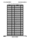
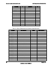
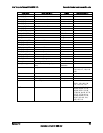
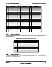
Pin
Signal Name
Pin
Signal Name
Pin
Signal Name
B4
XE_P1_B_TXP
F4
12V (BL_PWR_ON)
J4
GND
B5
XE_P1_C_RXN
F5
GND
J5
reserved
B6
XE_P1_C_TXP
F6
XE_P2_B_TXN
J6
GND
B7
XE_P1_D_RXN
F7
GND
J7
reserved
B8
XE_P1_D_TXP
F8
XE_P2_A_TXN
J8
GND
C1
GND
G1
SAS_P1_RXP
K1
SMB_SDA_A
C2
XE_P1_A_TXN
G2
GND
K2
FM_BL_SLOT_ID0
C3
GND
G3
XE_P2_C_RXP
K3
FM_BL_SLOT_ID3
C4
XE_P1_B_TXN
G4
GND
K4
FM_BL_SLOT_ID4
C5
GND
G5
SAS_P2_RXP
K5
reserved
C6
XE_P1_C_TXN
G6
GND
K6
reserved
C7
GND
G7
spare
K7
reserved
C8
XE_P1_D_TXN
G8
GND
K8
reserved
D1
XE_P2_D_RXP
H1
SAS_P1_RXN
L1
GND
D2
GND
H2
SAS_P1_TXP
L2
FM_BL_SLOT_ID1
D3
SMB_SCL_B
H3
XE_P2_C_RXN
L3
GND
D4
GND
H4
XE_P2_C_TXP
L4
FM_BL_PRES_N
D5
XE_P2_B_RXP
H5
SAS_P2_RXN
L5
GND
D6
GND
H6
SAS_P2_TXP
L6
reserved
D7
XE_P2_A_RXP
H7
spare
L7
GND
D8
GND
H8
spare
L8
reserved
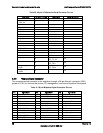
5.3.4 Serial Port Connector
The compute module provides one internal 9-pin Serial port header (J4K1). The following table
defines the pin-out.
Table 22. Internal 9-pin Serial Header Pin-out (J4K1)
Pin
Signal Name
Description
1
SPA_DCD
DCD (carrier detect)
2
SPA_DSR
DSR (data set ready)
3
SPA_SIN_L
RXD (receive data)
4
SPA_RTS
RTS (request to send)
5
SPA_SOUT_N
TXD (transmit data)
6
SPA_CTS
CTS (clear to send)
7
SPA_DTR
DTR (data terminal ready)
8
SPA_RI
RI (ring Indicate)
9
GND
Ground
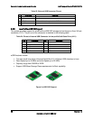
5.3.5 USB 2.0 Connectors
The following table details the pin-out of the external USB connectors (J1K2, J1K3) found on the
front edge of the compute module.