Connector/Header Locations and Pin-outs Intel
®
Compute Module MFS2600KI TPS
Revision 1.0
Intel order number: G51989-002
38
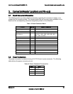
Table 23. External USB Connector Pin-out
Pin
Signal Name
Description
1
+5V
USB_PWR
2
USB_N
Differential data line paired with DATAH0
3
USB_P
(Differential data line paired with DATAL0
4
GND
Ground
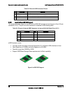
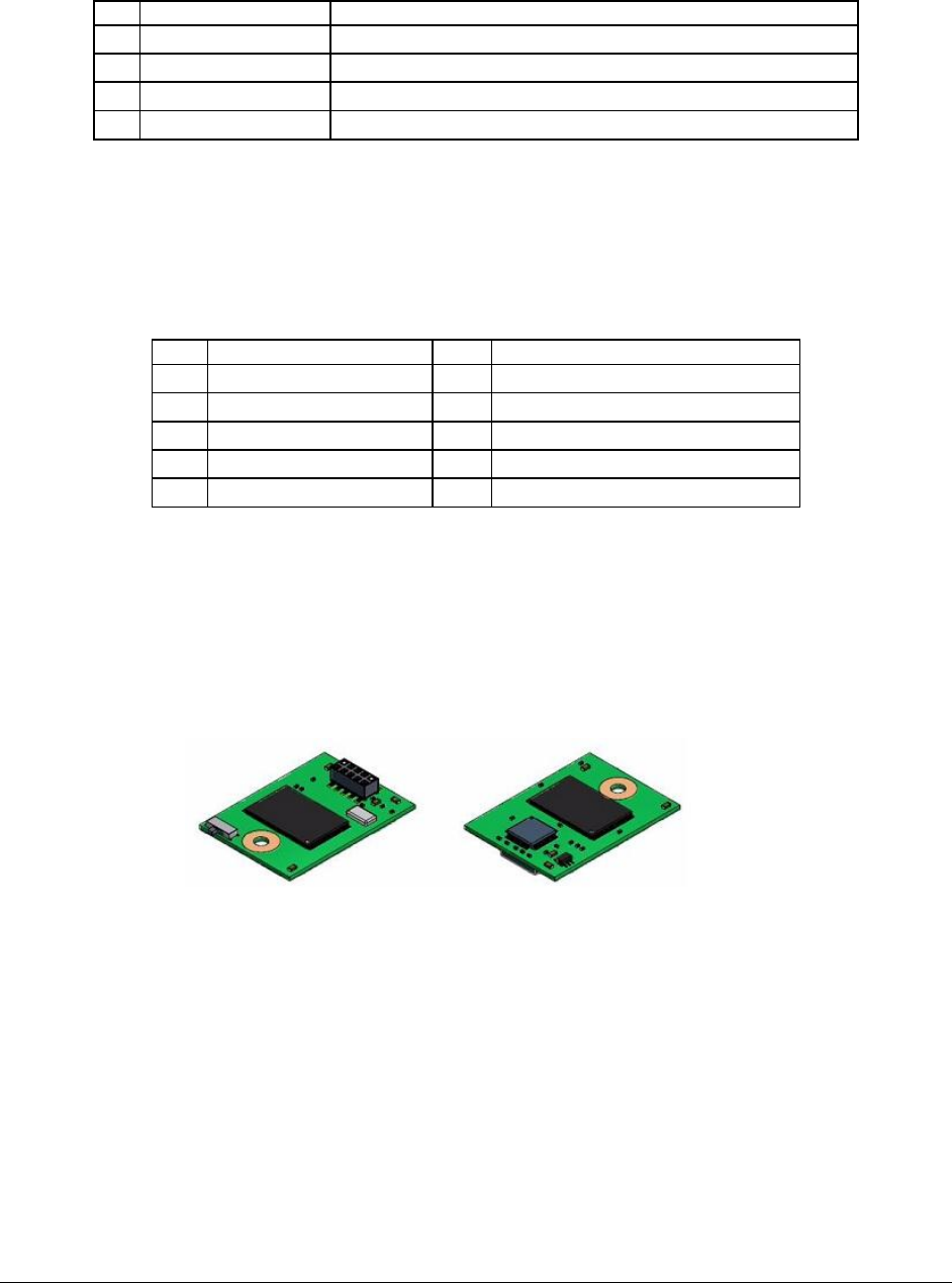
5.3.6 Low Profile eUSB SSD Support
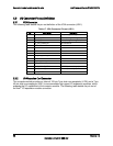
The system provides support for a low profile eUSB SSD storage device through a 2mm 2x5-pin
connector (J1K1). The pin-out of the connector is detailed in the following table.
Table 24. Pin-out of Internal USB Connector for low-profile Solid State Drive (J1K1)
Pin
Signal Name
Pin
Signal Name
1
+5V
2
NC
3
USB_N
4
NC
5
USB_P
6
NC
7
GND
8
NC
9
Key Pin
10
LED#
eUSB features include:
Two wire small form factor Universal Serial Bus 2.0 (Hi-Speed USB) interface to host.
Read Speed up to 35 MB/s and write Speed up to 24 MB/s.
Capacity range from 256GB to 32GB.
Support USB Mass Storage Class requirements for Boot capability.
Figure 8. eUSB SSD Support


