


Intel
®
Compute Module MFS2600KI TPS Appendix B: POST Code Diagnostic LED Decoder
Revision 1.0 Intel Confidential
Intel order number: G51989-002
45
Appendix B: POST Code Diagnostic LED Decoder
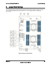
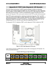
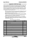
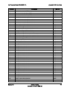
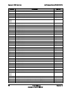
During the system boot process, the BIOS executes a number of platform configuration
processes, each of which is assigned a specific hex POST code number. As each configuration
routine is started, the BIOS displays the POST code to the POST Code Diagnostic LEDs on the
back edge of the server board. To assist in troubleshooting a system hang during the POST
process, the Diagnostic LEDs can be used to identify the last POST process that was executed.
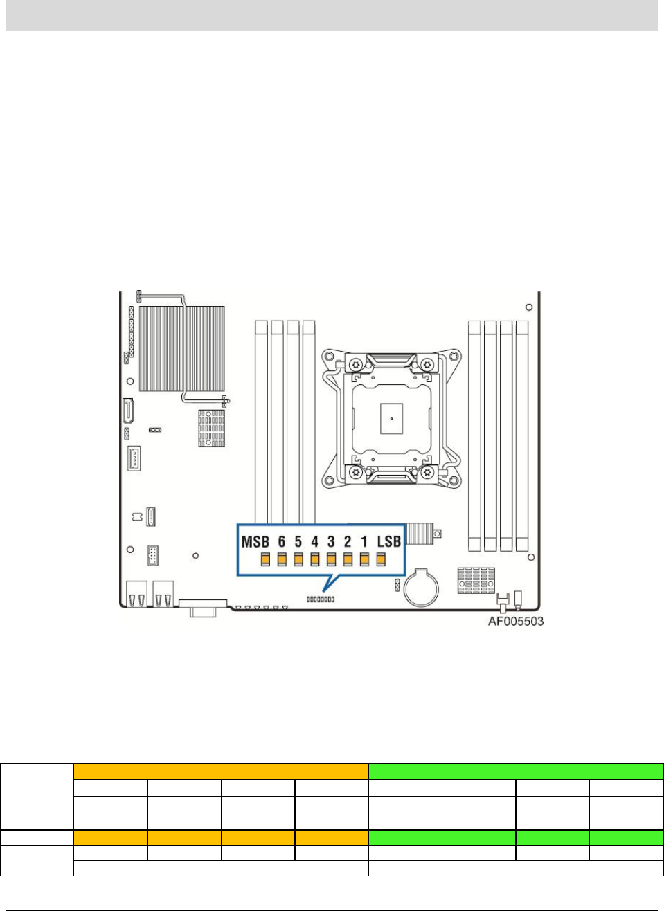
Each POST code is represented by a sequence of eight amber diagnostic LEDs. The POST
codes are divided into two nibbles, an upper nibble and a lower nibble. The upper nibble bits are
represented by diagnostic LEDs #4, #5, #6, and #7. The lower nibble bits are represented by
diagnostics LEDs #0, #1, #2, and #3. If the bit is set in the upper and lower nibbles, then the
corresponding LED is lit. If the bit is clear, then the corresponding LED is off.
The diagnostic LED #7 is labeled as “MSB”, and the diagnostic LED #0 is labeled as “LSB”.
Figure 10. POST Code Diagnostic LED Decoder
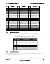
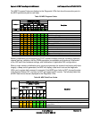
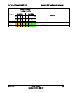
In the following example, the BIOS sends a value of ACh to the diagnostic LED decoder. The
LEDs are decoded as follows:
Table 26. POST Progress Code LED Example
LEDs
Upper Nibble AMBER LEDs
Lower Nibble GREEN LEDs
MSB
LSB
LED #7
LED #6
LED #5
LED #4
LED #3
LED #2
LED #1
LED #0
8h
4h
2h
1h
8h
4h
2h
1h
Status
ON
OFF
ON
OFF
ON
ON
OFF
OFF
Results
1
0
1
0
1
1
0
0
Ah
Ch