


Connector/Header Locations and Pin-outs Intel
®
Compute Module MFS2600KI TPS
Revision 1.0
Intel order number: G51989-002
32
5.3 I/O Connector Pin-out Definition
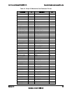
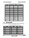
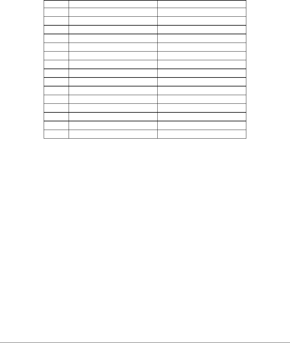
5.3.1 VGA Connector
The following table details the pin-out definition of the VGA connector (J2K1).
Table 17. VGA Connector Pin-out (J2K1)
Pin
Signal Name
Description
1
V_IO_R_CONN
Red (analog color signal R)
2
V_IO_G_CONN
Green (analog color signal G)
3
V_IO_B_CONN
Blue (analog color signal B)
4
TP_VID_CONN_B4
No connection
5
GND
Ground
6
GND
Ground
7
GND
Ground
8
GND
Ground
9
P5V_VID_CONN_9
P5V
10
GND
Ground
11
TP_VID_CONN_B11
No connection
12
V_IO_DDCDAT
DDCDAT
13
V_IO_HSYNC_CONN
HSYNC (horizontal sync)
14
V_IO_VSYNC_CONN
VSYNC (vertical sync)
15
V_IO_DDCCLK
DDCCLK
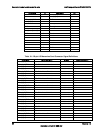
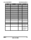
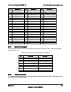
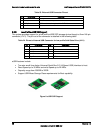
5.3.2 I/O Mezzanine Card Connector
The compute module provides an internal 120-pin Tyco dual-row receptacle (J1D2) and a Tyco
40-pin dual-row receptacle (J2A1) to accommodate high-speed I/O expansion modules, which
expands the I/O capabilities of the compute module. The following table details the pin-out of
the Intel
®
I/O expansion module connector.