


Intel Mobile Board MGM45WU Product Guide
42
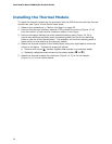
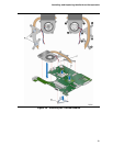
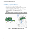
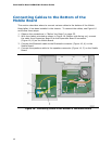
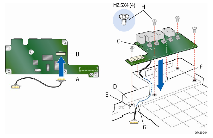
Installing Expansion Board A
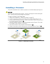
To install Expansion Board A in the D-tray, see Figure 13 and follow these steps:
1. Observe the precautions in "Before You Begin" on page 35.
2. Con
nect the Expansion Board A cable connector (Figure 13, A) to the connector
(Figure 13, B) on the bottom of Expansion Board A.
3. Place E
xpansion Board A (Figure 13, C) into the D-tray (Figure 13, D) on the
matchi
ng standoffs (Figure 13, E). Make sure that the
I/O ports align with the
chassis I/O port openings and the alignment pin (Figure 13, F).
4. Route the
Expansion Board A cable (Figure 13, G) through the chassis as shown in
the fi
gure.
5. Secure Expansion Board A to the D-tray with four screws (Figure 13, H) as shown.
Figure 13. Installing Expansion Board A in the D-tray