


List of Figures
Intel
®
Server System R1000GZ/GL Service Guide ix
List of Figures
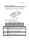
Figure 1. Intel
®
Server System R1000GZ/GL .............................................................................................. 1
Figure 2. Intel
®
Server System R1000GZ/GL Components ......................................................................... 3
Figure 3. 3.5" Hard Drive Bay - 4 Drive Configuration ............................................................................... 3
Figure 4. 2.5" Hard Drive Bay - 8 Drive Configuration ............................................................................... 3
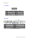
Figure 5. Front Panel Options ....................................................................................................................... 4
Figure 6. Back Panel Feature Identification .................................................................................................. 4
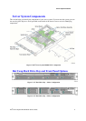
Figure 7. Server Board Connector and Component Locations ..................................................................... 5
Figure 8. Intel
®
Light-Guided Diagnostic LEDs - Server Board .................................................................. 6
Figure 9. Configuration Jumpers .................................................................................................................. 8
Figure 10. Optional Peripherals (8x2.5-inch hard drive bays as shown) ...................................................... 9
Figure 11. Front view of Front Bezel .......................................................................................................... 10
Figure 12. 4 x 3.5-inch Hard Drive Backplane Components (Front View) ................................................ 10
Figure 13. 4 x 3.5-inch Hard Drive Backplane Components (Rear View) ................................................. 11
Figure 14. 8 x 2.5-inch Hard Drive Backplane Components (Front View) ................................................ 11
Figure 15. 8 x 2.5-inch Hard Drive Backplane Components (Rear View) ................................................. 11
Figure 16. Cable Routing – 4 x 3.5” HDD .................................................................................................. 14
Figure 17. Cable Routing – 8 x 2.5” HDD .................................................................................................. 15
Figure 18. System Fan Order ...................................................................................................................... 16
Figure 20. Removing the Front Bezel ......................................................................................................... 17
Figure 21. Installing the Front Bezel .......................................................................................................... 17
Figure 22. Removing the System Cover ..................................................................................................... 18
Figure 23. Installing the System Cover ....................................................................................................... 18
Figure 24. Removing the Air Duct .............................................................................................................. 19
Figure 25. Installing the Air Duct ............................................................................................................... 19
Figure 26. Removing Processor Heatsink ................................................................................................... 20
Figure 27. Installing Processor – Open the Socket Lever ........................................................................... 21
Figure 28. Installing Processor – Open the Load Plate ............................................................................... 21
Figure 29. Installing Processor – Install the Processor ............................................................................... 21
Figure 30. Installing Processor – Remove the Cover .................................................................................. 22
Figure 31. Installing Processor – Close the Load Plate .............................................................................. 22
Figure 32. Installing Processor – Latch the Locking Lever ........................................................................ 22
Figure 33. Installing Processor Heatsink .................................................................................................... 23
Figure 34. Installing Memory ..................................................................................................................... 24
Figure 35. Installing Hard Disk Drive – Removing 3.5” HDD carrier ....................................................... 24
Figure 36. Installing Hard Disk Drive – Removing 3.5” HDD interface bracket ....................................... 25
Figure 37. Installing Hard Disk Drive – Installing 3.5” HDD .................................................................... 25
Figure 38. Installing Hard Disk Drive – Installing 2.5” HDD .................................................................... 25
Figure 39. Installing Hard Disk Drive – Inserting 3.5” HDD assembly ..................................................... 26
Figure 40. Installing Hard Disk Drive – Removing 2.5” HDD carrier ....................................................... 26
Figure 41. Installing Hard Disk Drive – Removing plastic drive blank ..................................................... 26
Figure 42. Installing Hard Disk Drive – Installing 2.5” HDD .................................................................... 27
Figure 43. Installing Hard Disk Drive – Inserting 2.5” HDD assembly ..................................................... 27
Figure 44. Removing PCI Riser Assembly ................................................................................................. 27
Figure 45. Installing PCI Riser Assembly .................................................................................................. 28
Figure 46. Installing a PCI Add-In Card ..................................................................................................... 29
Figure 47. Removing a PCI Add-In Card ................................................................................................... 29
Figure 48. Removing the PCI Riser Card ................................................................................................... 30