


SE7221BK1-E Technical Product Specification
Revision 1.3
18
For the NIC 2 connector (SE7221BK1LX sku only), the yellow LED indicates network
connection when on, and Transmit/Receive activity when blinking. The orange LED indicates
1000-Mbps operation when lit, the green LED indicates 100-Mbps operation when lit and 10-
Mbps when off.
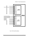
5.4 Interrupt Routing
The board interrupt architecture accommodates both PC-compatible PIC mode and APIC mode
interrupts through use of the integrated I/O APICs in the ICH6.
5.4.1 Legacy Interrupt Routing
For PC-compatible mode, the ICH6 provides two 82C59-compatible interrupt controllers. The
two controllers are cascaded with interrupt levels 8-15 entering on level 2 of the primary
interrupt controller (standard PC configuration). A single interrupt signal is presented to the
processors, to which only one processor will respond for servicing. The ICH6R contains
configuration registers that define which interrupt source logically maps to I/O APIC INTx pins.
The ICH6 handles both PCI and IRQ interrupts. The ICH6R translates these to the APIC bus.
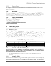
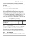
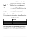
The numbers in the table below indicate the ICH6R PCI interrupt input pin to which the
associated device interrupt (INTA, INTB, INTC, INTD, INTE, INTF, INTG, INTH for PCI bus and
PXIRQ0, PXIRQ1, PXIRQ2, PXIRQ3 for PCI-X bus) is connected. The ICH6R I/O APIC exists
on the I/O APIC bus with the processors.
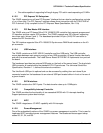
Table 13. PCI AND PCI-X Interrupt Routing/Sharing
Interrupt INT A INT B INT C INT D
Intel® 82541PI PIRQC
PCI Slot 1 (PCI 32b/33M)
PIRQF PIRQG PIRQE PIRQH
PCI Slot 4 (64b/66M)/ PCI Slot 6
(64bit/100MHz) (Riser,
SE7221BK1LX sku only)
PXIRQ0 PXIRQ1 PXIRQ2 PXIRQ3
PCI Slot 5 (64b/66M
PXIRQ5 PXIRQ6 PXIRQ7 PXIRQ4
5.4.2 APIC Interrupt Routing
For APIC mode, the baseboard interrupt architecture incorporates three Intel
®
I/O APIC devices
to manage and broadcast interrupts to local APICs in each processor. The Intel® I/O APICs
monitor each interrupt on each PCI device; including PCI slots in addition to the ISA
compatibility interrupts IRQ (0-15).
When an interrupt occurs, a message corresponding to the interrupt is sent across a three-wire
serial interface to the local APICs. The APIC bus minimizes interrupt latency time for
compatibility interrupt sources. The I/O APICs can also supply greater than 16 interrupt levels to
the processor(s). This APIC bus consists of an APIC clock and two bidirectional data lines.
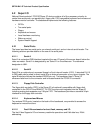
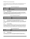
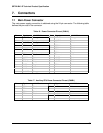
5.4.2.1 Legacy Interrupt Sources
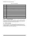
The table below recommends the logical interrupt mapping of interrupt sources on the board.
The actual interrupt map is defined using configuration registers in the ICH6.