SE7221BK1-E Technical Product Specification
Revision 1.3
viii
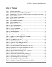
List of Tables
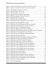
Table 1. Processor Support Matrix ..............................................................................................6
Table 2. Memory Bank Labels and DIMM Population Order........................................................8
Table 3. Characteristics of Dual/Single Channel Configuration with/without Dynamic Mode ......9
Table 4. Supported DDR2 modules...........................................................................................10
Table 5. PCI Bus Segment Characteristics................................................................................14
Table 6. P32-A Configuration IDs ..............................................................................................15
Table 7. P32-A Arbitration Connections.....................................................................................15
Table 8. P32-B Configuration IDs ..............................................................................................15
Table 9. P32-B Arbitration Connections.....................................................................................16
Table 10. P64-C Configuration IDs............................................................................................16
Table 11. P64-C Arbitration Connections ..................................................................................16
Table 12. PCI-E x 8 Connections..............................................................................................17
Table 13. PCI AND PCI-X Interrupt Routing/Sharing.................................................................18
Table 14. Interrupt Definitions....................................................................................................19
Table 15. Supported Wake Events ............................................................................................24
Table 16. Power Connector Pin-out (CN4H1)............................................................................25
Table 17. Auxiliary CPU Power Connector Pin-out (CN4B1).....................................................25
Table 18. HSBP Header Pin-out (J1D1) ....................................................................................26
Table 19. LCD Header Pin-out (J1C1).......................................................................................26
Table 20. LEGEND SE_LINK Header Pin-out (J2B1)................................................................26
Table 21. Front Panel 34-Pin Header Pin-out (J1J1).................................................................26
Table 22. VGA Connector Pin-out (J8A1)..................................................................................27
Table 23. NIC1-82541PI(10/100/1000) Connector Pin-out (J5A1) ............................................27
Table 24. NIC2-82541PI (10/100/1000) Connector Pin-out (J6A1) ...........................................28
Table 25. ATA 40-pin Connector Pin-out (J3J1)........................................................................28
Table 26. SATA Connector Pin-out (J1G1, J1G2, J1J2, J2J1)..................................................29
Table 27. USB Connectors Pin-out (J5A1) ................................................................................29
Table 28. Optional USB Connection Header Pin-out (J4F1) .....................................................29
Table 29. Legacy 34-pin Floppy Connector Pin-out (JP3J1) .....................................................30
Table 30. External DB9 Serial A Port Pin-out (J8A1).................................................................30
Table 31. 9-pin Header Serial B Port Pin-out (J1B1).................................................................31
Table 32. Keyboard and Mouse PS/2 Connectors Pin-out (KM9A1) .........................................31


