


12
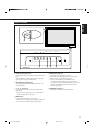
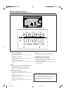
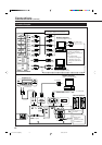
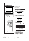
Connection Examples
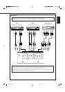
Connections (Continued)
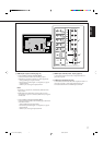
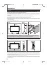
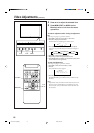
RGB connections
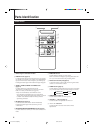
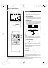
DISPLAY ASPECT POWER
RGB
COMPO.
VIDEO B
VOLUME
MULTIPLE
MODE ID SET
MONITORADJUSTMENT
VIDEO A
MUTING
MENU/EXIT
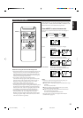
RM-C575 REMOTE CONTROL UNIT
ID
IN
RL
OUT
(RS232C)
(JVC CODE)
(120/230V)
SPEAKER OUT
RL
EXTERNALINTERNAL
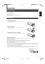
Remote control
Remote control
cable
(supplied)
When using
external
speakers, set this
to EXTERNAL.
To speaker input
terminals
Amplifier, etc.
To audio input
Power cord (supplied)
To a wall outlet
External speakers
Personal computer
(used to control the Monitor)
System connections
To audio output
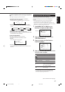
When connecting the RGB
terminals, set the RGB
INPUT setting correctly (see
page 23.)
• For audio signal
connections, change the
connection when you
change the RGB INPUT
setting.
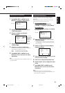
When connecting another Monitor, you
can use these RGB B OUT terminals
To R input
To G input
To B input
To HD/Cs input
To VD input
To monitor output
To audio output
To RS-232C
Personal computer 2
(used as the playback source)
Personal computer 1
(used as the playback source)
To VD output
To HD/Cs output
To B output
To G output
To R output
04-13.GD-V4210PZW[EN]/f 00.9.29, 5:54 PM12