


8
Parts Identification (Continued)
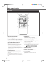
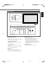
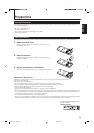
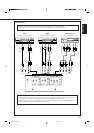
q VIDEO A terminals (page 13)*
• Video input terminal (BNC)
Connect this terminal to the video output terminal of a
VCR, etc.
• Video output terminal (BNC)
Connect this terminal to the video input terminal of
another Monitor.
• Audio input terminals (pin jack)
Connect these terminals to the audio input terminals of a
VCR, etc.
Note:
• Since the video output terminal on this Monitor is loop-
though terminals, the devices connected to this video
output terminal should be correctly terminated.
Otherwise, pictures become abnormally bright.
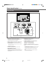
w VIDEO B terminals (page 13)*
• Y/C (S video) input terminal (Y/C terminal)
Connect this terminal to the S-video output terminal of a
VCR, etc.
• Video input terminal (pin jack)
Connect this terminal to the video output terminal of a
VCR, etc.
• Audio input terminals (pin jack)
Connect these terminals to the audio output terminals of
a VCR, etc.
Note:
* GD-V4210PCE, GD-V4210PCE-G, and GD-V4211PCE do
not have the following input terminals – VIDEO A,
VIDEO B, and COMPONENT. To input video, S-video,
and component signals, you need to install video
interface kit (IF-C421P1W), which is separately
purchased.
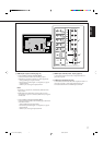
qw e
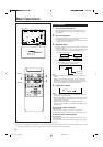
Note:
• When both the video and S-video terminals are
connected, the S-video terminal will have priority.
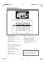
e COMPONENT input terminals (page 13)*
• Y, P
B/B-Y, PR/R-Y input terminals (BNC)
Connect these terminals to the component signal output
terminals of NTSC or high-vision equipment.
• Audio input terminals (pin jack)
Connect these terminals to the audio output terminals of
the other equipment.
04-13.GD-V4210PZW[EN]/f 00.9.29, 5:54 PM8