


31
ENGLISH
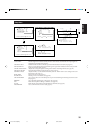
Serial Connections and Operations
When the Monitors are serially connected, you can control all of them at the same time (simultaneous operation) or control them
one by one separately (individual operation).
For individual operation, you have to assign an ID number to each of the Monitors.
For the purpose of explanation, we will call Monitor 1 as a Master and Monitor 2 and subsequent Monitors as Slaves.
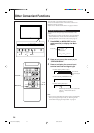
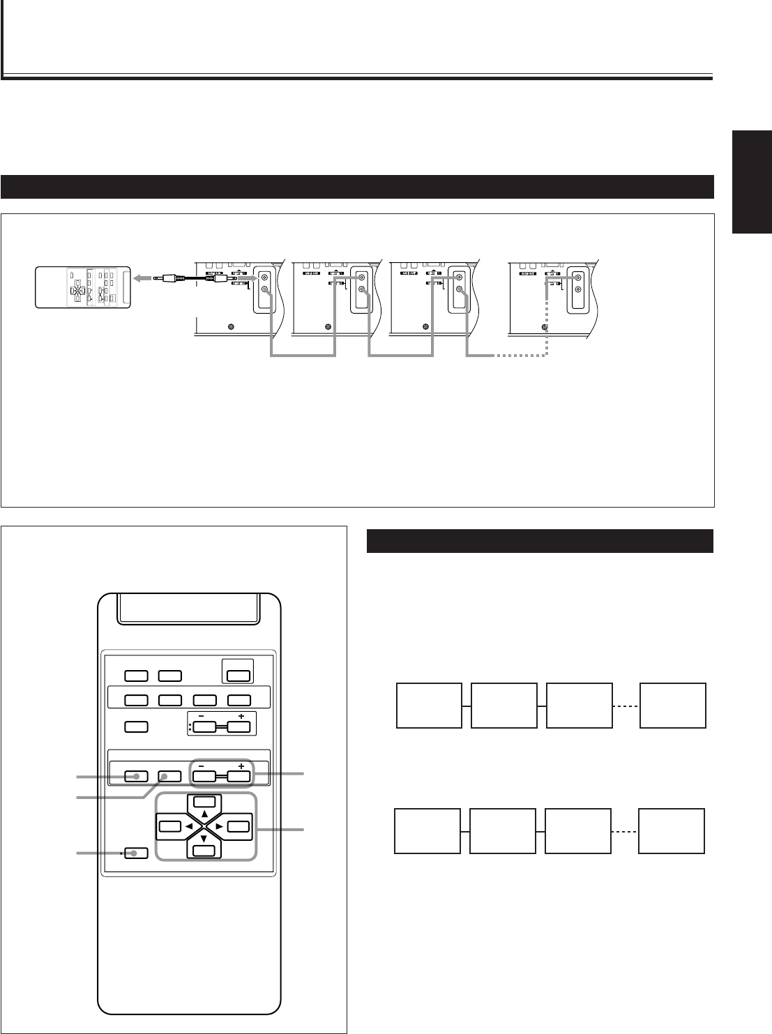
Connecting the Remote Control Cables
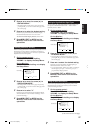
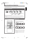
Remote control
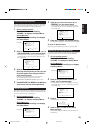
Assigning ID Numbers
The following procedure should be performed slowly and
securely.
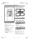
1
Turn on all the connected Monitors.
2
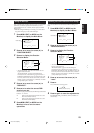
Press MODE.
On Master Monitor screen, “MASTER” is displayed, and
“[00]” is displayed on all of Slave Monitor screens.
3
Press ID SET.
On the Slave Monitor screens, “[01]”, “[02]”, “[03]”, ——
and so on will be displayed in the order of connection.
Notes:
• When a maximum number of 20 Monitors are connected, it
will take approx. 10 seconds for ID numbers to be displayed
on all the screens.
• If “[00]” is displayed on all the Monitor screens or if some
of the Monitors have no indication in step 1, press MODE to
turn off the indications on all Monitor screens, and then
press MODE again.
MASTER
[01] [02] [XX]
MASTER
[00] [00] [00]
Slave 2
Master
Slave 1
Slave XX
Slave 2
Master
Slave 1
Slave XX
Remote control cable
(supplied with
Monitor 2)
Remote control cable
(supplied with
Monitor 1)
Remote control cable
(supplied with
Monitor 3)
Notes:
• Do not connect the last monitor to Monitor 1.
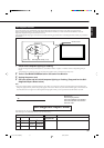
• When operating with a wired remote control, connect it to the REMOTE 2 (JVC CODE) input terminal of Monitor 1.
• When Monitors are serially connected, Monitor 2 and subsequent Monitors cannot be directly controlled with a wireless
remote control.
• Even after the Monitors are serially connected, each of them can be operated using the buttons on the Monitor. However,
you cannot perform simultaneous or individual operation even with the buttons on Master Monitor.
IN
RL
OUT
(RS232C)
(JVC CODE)
(120/230V)
SPEAKER OUT
RL
EXTERNALINTERNAL
IN
RL
OUT
(RS232C)
(JVC CODE)
(120/230V)
SPEAKER OUT
RL
EXTERNALINTERNAL
IN
RL
OUT
(RS232C)
(JVC CODE)
(120/230V)
SPEAKER OUT
RL
EXTERNALINTERNAL
IN
RL
OUT
(RS232C)
(JVC CODE)
(120/230V)
SPEAKER OUT
RL
EXTERNALINTERNAL
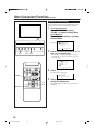
DISPLAYASPECT POWER
RGB
COMPO.
VIDEO B
VOLUME
MULTIPLE
MODE ID SET
MONITORADJUSTMENT
VIDEO A
MUTING
MENU/EXIT
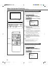
RM-C575 REMOTE CONTROL UNIT
ID
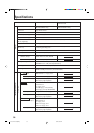
Remote control
cable (supplied)
Monitor 1
(Master)
Monitor 2
(Slave)
Monitor 3
(Slave)
Monitor XX
(Slave)
• When performing simultaneous or individual operation,
use the remote control.
MENU/EXIT
MODE
ID SET
ID +/–
2 / 3
5 /
5
DISPLAY ASPECT POWER
RGB
COMPO.
VIDEO B
VOLUME
MULTIPLE
MODE ID SET
MONITOR ADJUSTMENT
VIDEO A
MUTING
MENU/EXIT
RM-C575 REMOTE CONTROL UNIT
ID
31-40.GD-V4210PZW[EN]/f 00.9.29, 5:56 PM31