


6
Parts Identification (Continued)
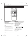
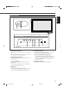
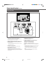
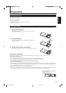
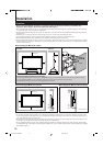
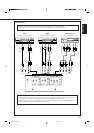
Monitor: Rear Views
1 AUDIO output terminal (pin jack) (page 12)
Connect these terminals to the audio input terminals of
external equipment such as an amplifier.
2 REMOTE 1 (RS232C) terminal (D-sub, 9-pin) (page 12)
Connect this terminal to the RS-232C terminal of a
personal computer.
• For the control method using this terminal, consult an
authorized JVC dealer.
3 AC INPUT terminal (page 12)
Connect the supplied power cord to this terminal.
4 MAIN POWER switch (page 14)
Setting this switch to ON will put the Monitor into
standby mode, allowing you to turn on and off the power
using the POWER button either on the remote control or
on the Monitor.
5 SPEAKER OUT terminals (page 12)
Connect external speakers.
6 INTERNAL/EXTERNAL (built-in speaker/external
speaker) selecting switch (page 12)
INTERNAL: To use built-in speakers.
EXTERNAL: To use external speakers.
7 REMOTE 2 (JVC CODE) terminals (mini jack) (page 31)
• IN
For Master Monitor: Connect a wired remote control to
this terminal for serial connection.
For Slave Monitors: Connect to the REMOTE 2 OUT
terminal of another Monitor in serial connection.
• OUT
Connect to the REMOTE 2 IN terminal of another
Monitor for serial connection.
IN
RL
OUT
(RS232C)
(JVC CODE)
(120/230V)
SPEAKER OUT
RL
EXTERNALINTERNAL
4
3
2
1
5
6
7
04-13.GD-V4210PZW[EN]/f 00.9.29, 5:54 PM6