Chapter 4---Maintenance (Removal/Replacement)
2. Remove the 2 flathead screws that secure the VIC to the
projector rear panel.
3. Grasp the VIC connector bracket and pull the VIC out
(Wiggle the VIC a little, if necessary, to extract it).
4.12 Video Amplifier PCB
The Video Amplifier PCB for the 3 CRTs is located under the
Electronic Module, on the bottom frame of the projector behind and
under the CRT assemblies.
To remove a Video Amplifier PCB:
1. Remove the front and rear covers (Section 4.2).
2. Tilt the Electronic Module up (Section 3.3).
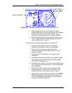
3. Loosen the Green CRT Holder Ring (knurled knob-see
Figure 3-5). Read the Caution below this step before
removing the CRT Holder Ring completely. NOTE: The
holder ring should only be hand-tight. If it cannot be
removed by hand, a flathead screwdriver can be used in
the slots on the CRT Holder Ring (Figure 3-5) to help
loosen it. Use care not to let the flathead screwdriver slip
out of the slot and possibly damage components. Do not
use a screwdriver or any other tool to tighten this ring-it
should be hand-tight only.
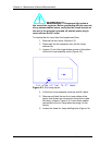
CAUTION! This step is performed with the CRT Socket
Connector still connected to the Green CRT and the ground
wire still connected from the CRT/Yoke Assembly to the CRT
Socket Connector. This is because the Green CRT Socket
Connector is close to the rear of the projector and is easier to
disconnect from the CRT after the CRT/Yoke Assembly is
loose and is moved away from the rear of the projector. Use
extreme care not to break any of these connections when
removing the CRT/Yoke Assembly.
4. Carefully remove the Green CRT/Yoke Assembly by
sliding it backward and upward as far as possible before
disconnecting the Green CRT Socket Connector from the
CRT neck. Use care to avoid bumping the CRT as it is
being removed and to avoid breaking any of the wires that
connect from the CRT Socket Connector to the Video
Amplifier.
5. Move the Green CRT/Yoke Assembly away from the rear
of the projector, then disconnect the Green CRT Socket
Connector and the ground wire between the CRT/Yoke
Assembly and the CRT Socket Connector. NOTE: It may
be helpful to perform this step with a partner-one person
to hold the CRT/Yoke Assembly firmly and the other to
remove the CRT Socket Connector and the ground wire.
6. Gently lay the Green CRT Socket Connector on the top of
the Video Amplifier PCB.
4-14 Model 200 Service Manual


