


Chapter 2---System Description
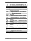
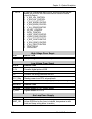
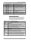
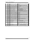
I 9 Left blanking Data for adjustment of left blanking
I 12 Top blanking Data for adjustment of top blanking
I 12 Bottom blanking Data for adjustment of bottom blanking
I 8 Horz. phase Data for adjustment of horizontal phase
I 12 Vert. phase Data for adjustment of vertical phase
O 3 Frequency bands The frequency band associated with the current
signal
O 1 /RTG_OK A low on this line indicates an operational RTG
board
O 2 RTG_MODEL The revision of the RTG board
O 12 H_COUNT The number of horizontal lines associated with
the current signal
O 12 V_COUNT Data for V_COUNT
O 3 INPUT_MODE Data indicating the selected sync signals
O 1 INTERLACE High indicates interlace pattern
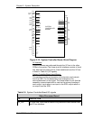
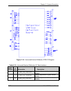
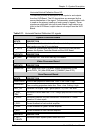
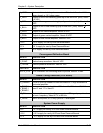
Raster Timing Generator Input/Output
This section describes the inputs to and outputs from the RTG
board. The I/O descriptions are arranged by the source and
destination of the signal. The assembly communicated with is
used as the primary heading of each output. Input refers to an
input to the RTG, output refers to an output from the RTG.
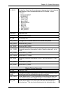
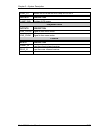
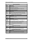
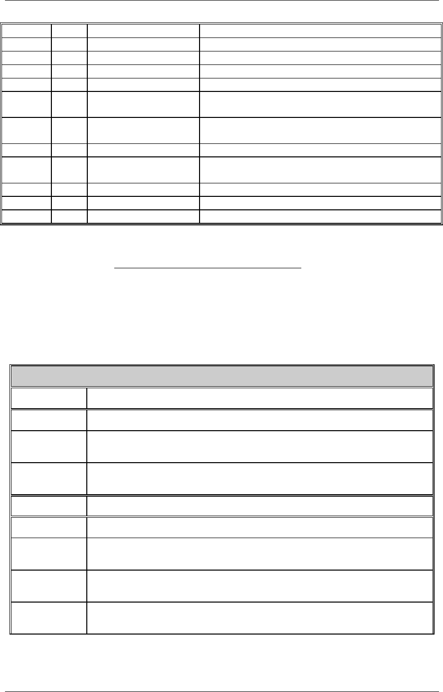
Table 2-11. Raster Timing Generator I/O signals
S
y
stem Controller Board
INPUTS DESCRIPTION
ISYNC_CLK 5 mHz clock used to generate the internal sync signals
IIC_CLK IIC clock line. Unidirectional clock line for control of synchronous
data transfer over the IIC bus interface
IIC_DATA IIC data line. Bi directional serial line for synchronous data transfer
between system control board and RTG board
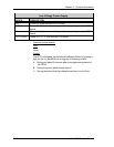
OUTPUTS DESCRIPTION
/IIC_INT IIC interrupt line. This is not used by the RTG board.
SOURCE_
VALID
This signal indicates a new source (or valid). A high indicates a valid
stable signal and low indicates change in input signal
ODD_FIELD Square wave with 50 % duty cycle which is low during the odd field
of an interlace signal. This signal is high for noninterlaced signals
280_CLK Square wave signal, 50 % duty cycle, 280 times the frequency of
horizontal sync. This clock is synchronized to the horizontal sync.
2-42 Model 200 Service Manual