


Chapter 2---System Description
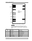
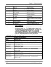
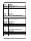
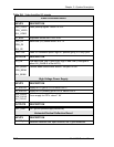
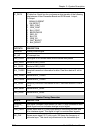
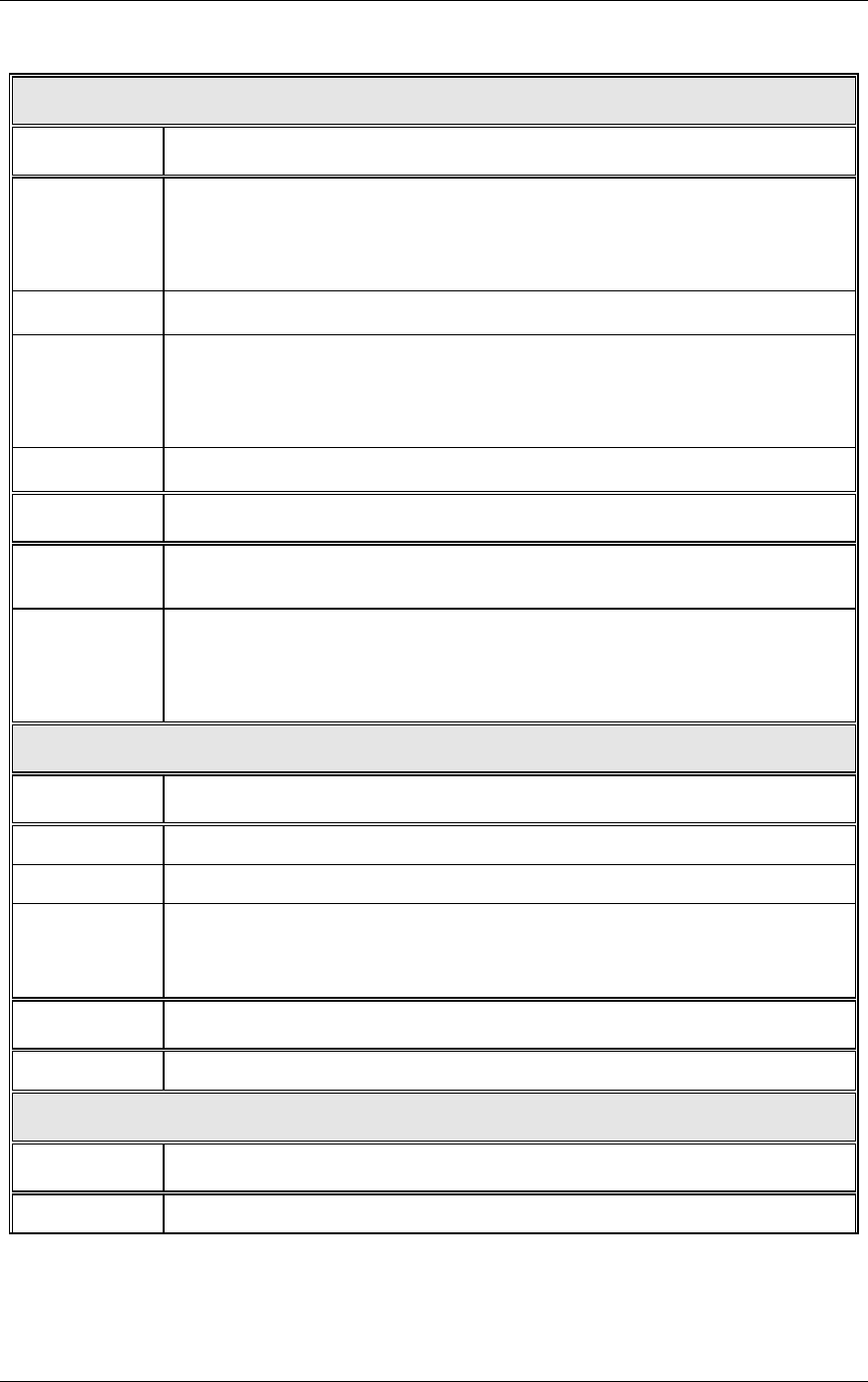
Table 2-8. Video Amplifier I/O signals
Video Processor Board
INPUTS DESCRIPTION
RED_VIDEO
GRN_VIDEO
BLU_VIDEO
Video preamp signals. About 0.5 VPP
G1_BIAS Brightness control line. 0 to 5 V DC
RED_G2
GRN_G2
BLU_G2
Black level (G2) control lines 0 to 3.1 V
RESTORE Video DC restoration pulse. logic HC positive going 4% duty cycle
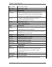
OUTPUTS DESCRIPTION
/VA_OK VAB status line. Low = good VAB. High = Bad VAB (This signal is
called /HV_ENABLE at the HVPS).
RED_BEAM
GRN_BEAM
BLU_BEAM
Cathode beam current lines. about 1 volt per 100 UA
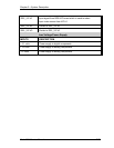
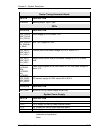
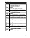
High Voltage Power Supply
INPUTS DESCRIPTION
G1_SUPPLY Supply for G1 grid of CRTs. About -200 V
G2_SUPPLY Supply for G2 (screen) grid of CRTs. About 1200 V
RED_FOCUS
GRN_FOCUS
BLU_FOCUS
Focus supply for CRTs. about 7 KV
OUTPUTS DESCRIPTION
ARC_GND CRT ground (anode supply return line)
Horizontal/Vertical Deflection Board
INPUTS DESCRIPTION
/SWEEP_OK
Deflection detection line. open collector, low = good deflection
2-32 Model 200 Service Manual