


Chapter 2---System Description
RED_VIDEO
GRN_VIDEO
BLU_VIDEO
BLANKING
G1 SUPPLY
G1 BIAS
RESTORE
ARC_GND
BLU_CATHODE 8
BLU_GRID1 9
BLU_GRID2 10
BLU_BEAM 16
BLU_HEAT- 7
BLU_HEAT+ 6
ARC_GND 3
GRN _CATHODE 8
GRN _GRID1 9
GRN _GRID2 10
GRN_BEAM 14
GRN _HEAT- 7
GRN _HEAT+ 6
ARC_GND 3
RED _CATHODE 8
RED _GRID1 9
RED _GRID2 10
RED_BEAM 12
RED _HEAT- 7
RED _HEAT+ 6
ARC _GND 3
2
4
6
23
21
1
2
13 GRN_G2
15 BLU_G2
1 G2 SUPPLY
11 RED_G2
19 /SWEEP_OK
3 + 8OV
7 + 15V
5 + 6.2V
9 -15V
/VA_OK 18
J83
J68
J68
J85
J87
J68
J68
J84-1,
J86-1,
J88-1
J67
J68
J69
J68
From
VPB
From VPB
From HVPS
From RTG
From VPB
From
VPB
From HVPS
From HVDB
From
LVPS
To VPB
To RED
CRT
To VPB
To GRN
CRT
To VPB
To BLU
CRT
To VPB
To
HVPS
VIDEO
AMPLIFIER
BOARD
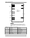
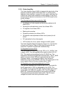
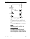
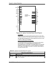
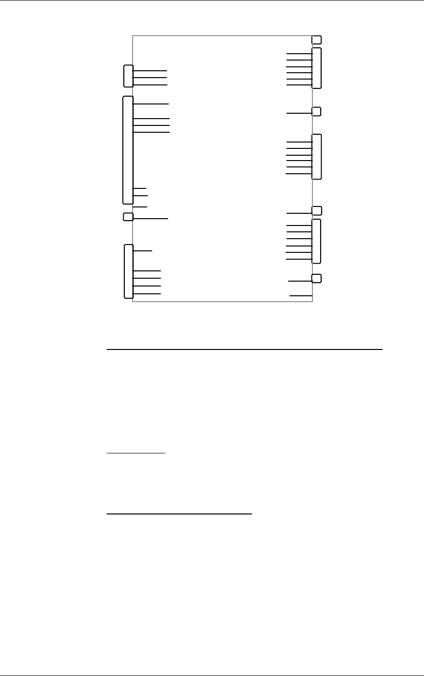
Figure 2-11. Video Amplifier PCB, Block Diagram.
CRT interface for Focus, heater voltages and ARC ground
The three CRT sockets are part of the VAB. They provide the
necessary interface for the input of the three CRTs. The Focus
voltage for each color is connected directly to the socket of each
CRT.
The VAB provides ARC grounds for each CRT which are used to
protect against arcing of the CRT anode supply.
IIC Interface
The VAB does not use the IIC interface. All adjustments are
accomplished by the control lines coming from the Video
Processor Board.
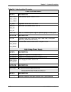
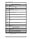
The Video Amplifier Board I/O
This section provides a description of the inputs to and outputs
from the VAB. The I/O descriptions are arranged by the
source/destination of the signal. The assembly communicated with
is used as the primary heading of each group of signals. Those
signals are subdivided into inputs and outputs. Input refers to an
Input to the VAB, output refers to an output from the VAB.
Model 200 Service Manual 2-31