


Chapter 2---System Description
IIC_CLK
IIC_DATA
/IIC_SINT
X_RED_CONV
X_GRN_CONV
X_BLU_CONV
Y_RED_CONV
Y_GRN_CONV
Y_BLU_CONV
V_DRIVE
CORR_SYNC
WIDTH_CONTROL
RED_ILA+
RED_ILA-
GRN_ILA+
GRN_ILA-
BLU_ILA+
BLU_ILA-
X_RED-
X_GRN+
X_GRN-
X_BLU+
X_BLU-
X_RED+
Y_RED-
Y_GRN+
Y_GRN-
Y_BLU+
Y_BLU-
Y_RED+
H_PARABOLA
V_PARABOLA
V_RAMP
V_PARAB
2
3
4
2
4
6
8
10
12
17
18
5
J33
J31
J32
5+5.1V
66ND
7+15V
9GND
11 -15V
13 GND
J32
14
15
J33
1
3
J31
J40
1
2
3
4
5
6
J39
1
2
3
4
5
6
J38
1
2
4
5
7
8
1
GND
13
GND
2
GND
1
GND
GND
16
FROM
SCB
FROM RTG
FROM
LVPS
TO
HVPS
FROM
HVDB
TO/FROM
SRB
TO/FROM
SRB
TO
ILAs
FROM HVDB
CONVERGENCE/
DEFLECTION
BOARD
FROM
SCB
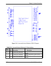
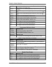
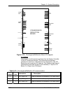
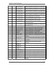
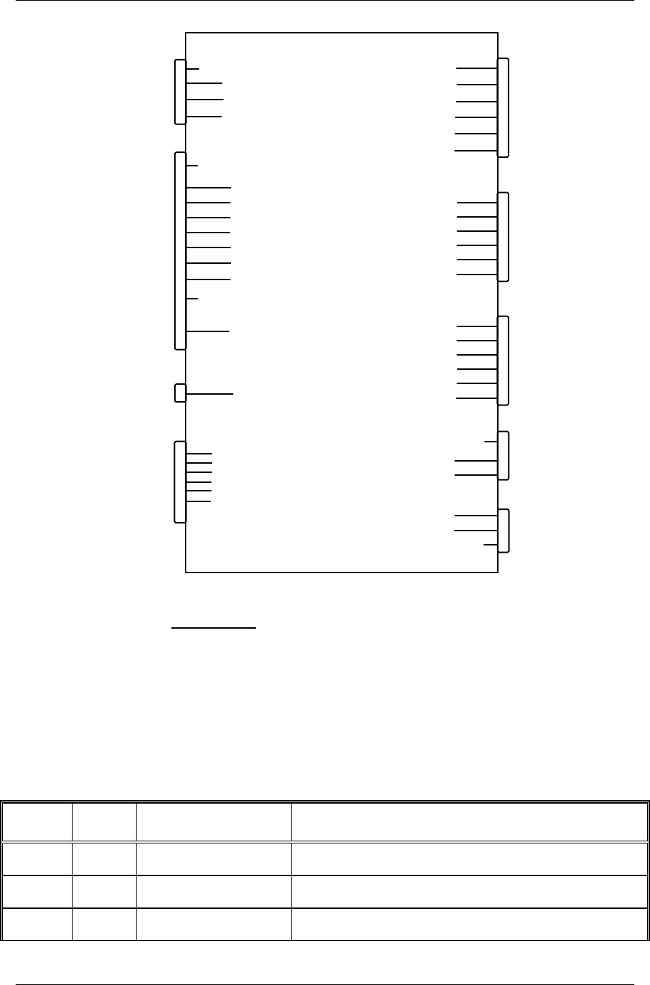
Figure 2-15. Convergence/Deflection Board I/O diagram.
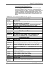
IIC interface
Adjustments for this board are performed by the System Controller
via the IIC serial bus interface. This three wire bus interface
consists of a clock line, a data line and an interrupt line. The C/D
Board does not create any IIC interrupt. The following table lists all
adjustments performed via the IIC bus interface (I = Input to C/D
Board, O = Output from C/D Board):
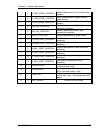
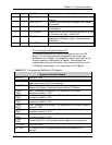
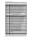
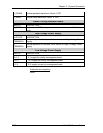
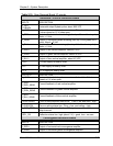
Table 2-12. Convergence/Deflection IIC communication
Input/
Output
No. of
bits
Information Description
I 1 ILA_FREQ_N1 Data for selection of frequency of ILA bias circuit
I 1 ILA_FREQ_N2 Data for selection of frequency of ILA bias circuit
I 1 ILA_FREQ_N3 Data for selection of frequency of ILA bias circuit
2-52 Model 200 Service Manual