


Chapter 2---System Description
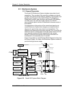
2.3 Electronics System
2.3.1 General Description
The Model 200 Electronics System includes nine printed circuit
assemblies. They provide all the controlling voltages and signals
to adjust and correct picture settings, geometry, convergence, and
shading (see Chapter 4 of the User’s Guide). The Electronics
System also controls video and sync input signals, LED displays
on PCBs at the rear and side of the projector, two RS-232
communications ports, and two IR receivers for remote control of
the projector.
The descriptions in this portion of the manual are based on an
overall Electronics System block diagram and simplified block
diagrams for each of the nine printed circuit assemblies. The
diagrams and descriptions serve two purposes; first, to provide the
technician with an overall grasp of how the system works and how
each assembly works with other assemblies in the system,
second, to provide the technician with enough information to
troubleshoot to the assembly level, if needed.
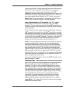
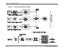
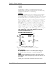
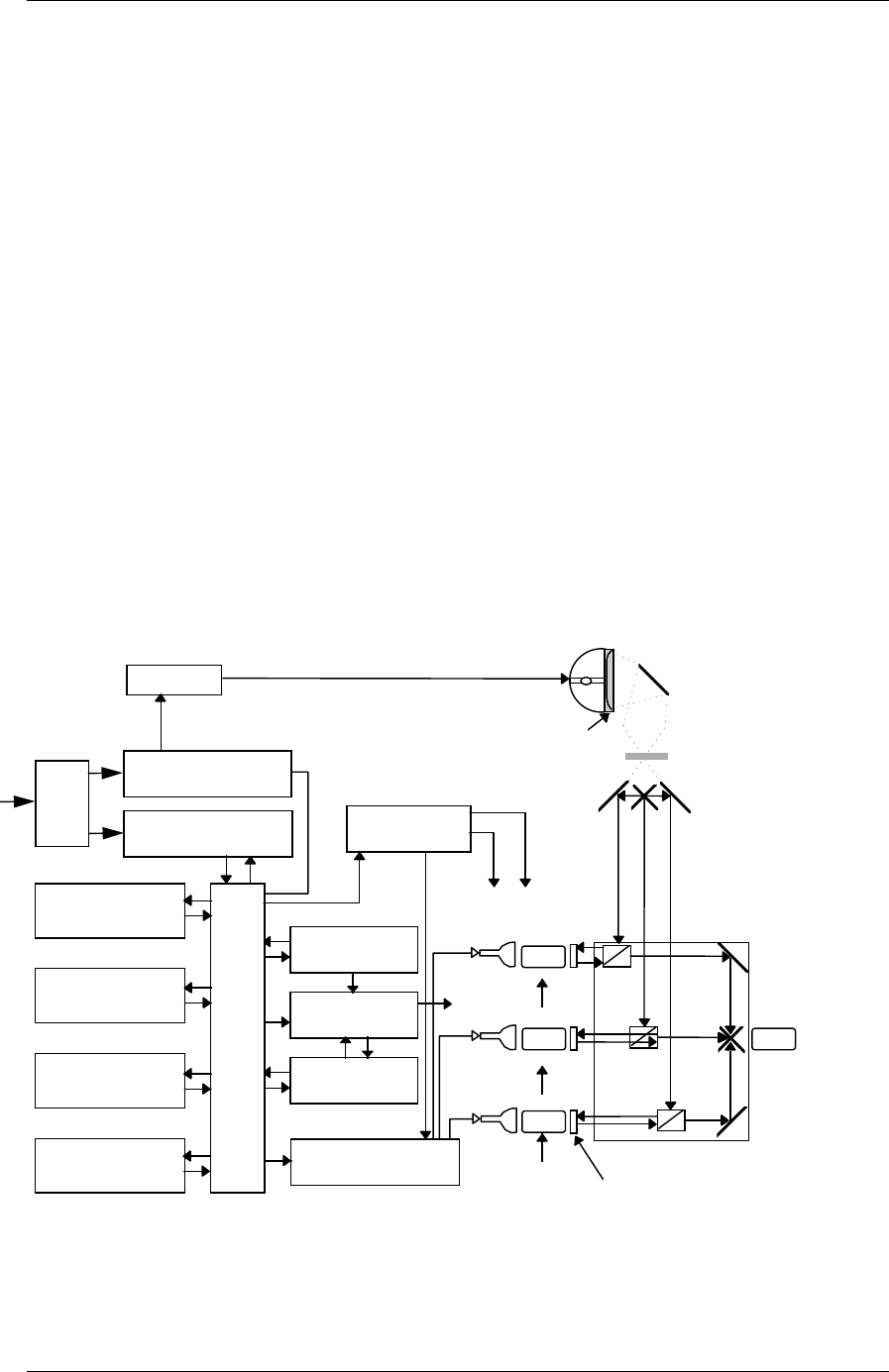
Figure 2-2 provides an overall System Block Diagram to show how
the Optical System, Arc Lamp, and Electronics System combine to
provide the bright screen image.
HORIZONTAL
VERTICAL
DEFLECTION
SCAN REVERSAL
CONVERGENCE
DEFLECTION
VIDEO INPUT
CARDS
VIDEO
PROCESSOR
RASTER TIMING
GENERATOR
SYSTEM
CONTROLLER
LINE
FILTER
AC
INPUT
LAMP
POWER SUPPLY
LOW VOLTAGE
POWER SUPPLY
VIDEO AMPLIFIERS
G2
ELECTRONICS MODULES
IGNITER
TO CRTS
FOCUS
HIGH
VOLTAGE
HIGH VOLAGE
POWER SUPPLY
CRTS
RELAY
LENSES
PROJECTION
LENS
OPTICS MODULE
ILA’S
CROSS
DICHROICS
UV FILTERS
INTEGRATOR
COLD MIRROR
LAMP
CONDENSING
LENS
B A C K P LA N E
TO YOKES
Figure 2-2. Model 200 System Block Diagram
Model 200 Service Manual 2-7