8: Setup Mode: Channel Configuration
Active Startup Mode Description
If present, the port number must follow the IP address, must be
presented as a decimal number in the range 1-65535, and must
be preceded by a forward slash (ASCII 0x2F). The slash
separates the IP address and the port number. If you omit the
port number from a command string, the internally stored remote
port number starts a connection.
If a partial IP address is presented in a command string, it is
interpreted to be the least significant bytes of the IP address and
uses the internally stored remote IP address to provide the most
significant bytes of the IP address. If the IP address entered is
0.0.0.0/0, the device server enters Monitor Mode.
For example, if the remote IP address already configured in the
unit is 129.1.2.3, then an example command string would be
C3/7. (This would connect to 129.1.2.3 and port 7.) You may
also use a different ending for the connection string. For
example, C50.1/23 would connect you to 129.1.50.1 and port 23.
If an IP address does not follow the first command string
character (which is "C"), the subsequent character string is
interpreted as the host name and domain to be used in DNS
lookup. This character string can include a destination port
number as well. The port number can be preceded by either a
forward slash (/) or a colon ( : ).
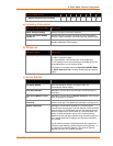
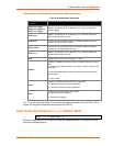
Table 8-7. Manual Connection Address Example
Command String Result if remote IP is 129.1.2.3 and remote port is 1234
C121.2.4.5/1
Complete override; connection is started with host 121.2.4.5,
port 1
C5
Connects to 129.1.2.5, port 1234
C28.10/12
Connects to 129.1.28.10, port 12
C0.0.0.0/0
Enters Monitor Mode
Cwww.lantronix.com/80
Tries to connect to the Lantronix web server if the
<hostname:domain> (www.lantronix.com) is configured in the
DNS server database.
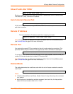
Autostart (Automatic
Connection)
If you enable Autostart, the unit automatically connects to the
remote IP address & remote port specified when the firmware
starts.
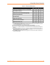
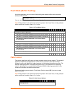
Hostlist
If you enable this option, the device server scrolls through the
hostlist until it connects to a device listed in the hostlist table.
Once it connects, the unit stops trying to connect to any others.
If this connection fails, the unit continues to scroll through the
table until it is able to connect to another IP in the hostlist.
Hostlist supports a minimum of 1 and a maximum of 12 entries.
Each entry contains the IP address and the port number.
The hostlist is disabled for Manual and Modem Modes. The unit
does not accept a data connection from a remote device when
the hostlist option is enabled.
Micro125 User Guide 46


