A: Binary to Hexadecimal Conversions 73
Converting Binary to Hexadecimal ______________________________________ 73
Conversion Table ________________________________________________ 73
Scientific Calculator ______________________________________________ 74
List of Figures
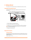
Figure 3-1. Evaluation Board Connected to Serial Device and Network ____________ 12
Figure 5-1. Web-Manager Login Window ____________________________________ 19
Figure 5-2. Lantronix Web-Manager ________________________________________ 19
Figure 5-3. Network Settings _____________________________________________ 20
Figure 5-4. Server Settings _______________________________________________ 23
Figure 5-5. Hostlist Settings ______________________________________________ 25
Figure 5-6. Channel Serial Settings ________________________________________ 26
Figure 5-7. TCP Connection Settings _______________________________________ 29
Figure 5-8. UDP Connection Settings _______________________________________ 32
Figure 5-9. Applying Settings _____________________________________________ 34
Figure 5-10. Applying Default Settings ______________________________________ 34
Figure 6-1. MAC Address ________________________________________________ 36
Figure 6-2. Setup Menu Options ___________________________________________ 36
Figure 8-1. Serial Port Parameters _________________________________________ 41
Figure 8-2. Hostlist Option _______________________________________________ 47
Figure 9-1. Expert Settings _______________________________________________ 56
Figure 9-2. Security Settings ______________________________________________ 58
Figure 10-1. TFTP Window _______________________________________________ 64
List of Tables
Table 7-1. BootP/DHCP/AutoIP options _____________________________________ 38
Table 7-2. Standard IP Network Netmasks __________________________________ 39
Table 8-1. Interface Mode Options _________________________________________ 42
Table 8-2. Common Interface Mode Settings _________________________________ 42
Table 8-3. Interface Mode Options _________________________________________ 43
Table 8-4. Flow Control Options ___________________________________________ 43
Table 8-5. Reserved Port Numbers ________________________________________ 43
Table 8-6. Connect Mode Options _________________________________________ 44
Table 8-7. Manual Connection Address Example _____________________________ 46
Table 8-8. Modem Modes ________________________________________________ 48
Table 8-9. Modem Mode Messages ________________________________________ 49
Table 8-10. Modem Mode Commands ______________________________________ 50
Table 8-11. Disconnect Mode Options ______________________________________ 52
Table 8-12. Flush Mode Options ___________________________________________ 53
Table 8-13. Pack Control Options __________________________________________ 53
Table 9-1. Expert Settings: Details Settings __________________________________ 56
Table 10-1. Firmware Files _______________________________________________ 63
Table 11-1. Monitor Mode Commands ______________________________________ 67
Table 11-2. Command Response Codes ____________________________________ 68
Micro125 User Guide 6


