


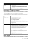


– If you directly connect two servers (without a hub), or if you are not using a hub with X ports, use a
crossover cable. To determine whether a hub has an X port, check the port label. If the label contains
an X, the hub has an X port.
• Determine whether the hub supports auto-negotiation. If it does not, try conguring the integrated
Ethernet controller manually to match the speed and duplex mode of the hub.
• Check the Ethernet controller LEDs on the rear panel of the server. These LEDs indicate whether there
is a problem with the connector, cable, or hub.
– The Ethernet link status LED is lit when the Ethernet controller receives a link pulse from the hub. If the
LED is off, there might be a defective connector or cable or a problem with the hub.
– The Ethernet transmit/receive activity LED is lit when the Ethernet controller sends or receives data
over the Ethernet network. If the Ethernet transmit/receive activity LED is off, make sure that the hub
and network are operating and that the correct device drivers are installed.
• Check the LAN activity LEDs on the rear of the server. The LAN activity LED is lit when data is active on
the Ethernet network. If the LAN activity LED is off, make sure that the hub and network are operating
and that the correct device drivers are installed.
• Check for operating-system-specic causes of the problem.
• Make sure that the device drivers on the client and server are using the same protocol.
If the Ethernet controller still cannot connect to the network but the hardware appears to be working, the
network administrator must investigate other possible causes of the error.
Solving undetermined problems
If the diagnostic tests did not diagnose the failure or if the server is inoperative, use the information in
this section.
If you suspect that a software problem is causing failures (continuous or intermittent), see “Software
problems” on page 95.
Damaged data in CMOS memory or damaged rmware can cause undetermined problems. To reset the
CMOS data, use the password switch 2 (SW4) to override the power-on password and clear the CMOS
memory; see “Locating parts on the system board” on page 14.
Check the LEDs on all the power supplies. If the LEDs indicate that the power supplies are working
correctly, do the following:
1. Turn off the server.
2. Make sure that the server is cabled correctly.
3. Remove or disconnect the following devices, one at a time, until you nd the failure. Turn on the server
and recongure it each time.
• Any external devices
• Surge-suppressor device (on the server)
• Modem, printer, mouse, and non-Lenovo devices
• Each adapter
• Hard disk drives
• Memory modules: the minimum conguration requirement is 1 GB DIMM per microprocessor (2 GB
in a two-microprocessor conguration)
The following minimum conguration is required for the server to start:
• One microprocessor
• One 1 GB DIMM
• One power supply
Chapter 7. Troubleshooting 97