


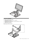
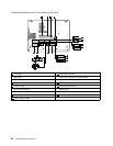
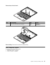

Step Screw (quantity) Color
Torque
2
M2 × 3 mm, wafer-head, nylon-coated (1) Silver
0.181 Nm
(1.85 kgf-cm)
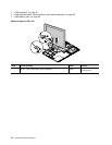
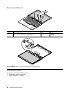
When installing: Ensure that the connector is attached rmly.
1110 System board and base cover assembly
Important notices for handling the system board
When handling the system board, bear the following in mind:
• The system board has an accelerometer, which can be broken if several thousands of G-forces are applied.
Note: Dropping a system board from a height of as little as six inches so that it falls at on a hard bench can subject
the accelerometer to as much as 6,000 G's of shock.
• Be careful not to drop the system board on a bench top that has a hard surface, such as metal, wood, or composite.
• If a system board is dropped, be sure to document the drop in any reject report, and replace the system board.
• Avoid rough handling of any kind.
• At every point in the process, be sure not to drop or stack the system board.
• If you put a system board down, be sure to put it only on a padded surface such as an ESD mat or a corrugated
conductive surface.
For access, remove these FRUs in order:
• “1010 Hard disk drive or solid-state drive” on page 58
• “1020 Keyboard” on page 60
• “1030 PCI Express Mini Card for wireless LAN” on page 62
• “1040 PCI Express Mini Card for wireless WAN or mSATA solid-state drive” on page 63
• “1050 Keyboard bezel, backup battery, and speaker assembly” on page 66
• “1100 DC-in connector” on page 77
• “1070 Proximity sensors” on page 70
• “1060 Battery pack” on page 69
• “1080 Thermal fan assembly and hard disk drive or solid-state drive connector” on page 72
• “1090 LCD unit” on page 73
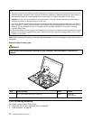
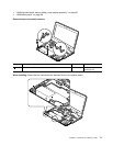
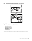
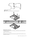
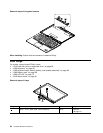
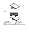
Removal steps of system board and base cover assembly
Attention: The following components soldered on the system board are extremely sensitive. When you
service the system board, avoid any kind of rough handling.
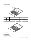
a b
78 Hardware Maintenance Manual