3
When installing:
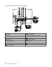
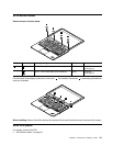
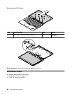
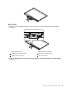
• When you pull the cables through the hole in the hinge, rout the cables as shown in the following
illustration.
4
5
6
3
2
1
1 Power cable assembly 4 Wireless WAN main antenna
2 Wireless WAN auxiliary antenna 5 Wireless LAN auxiliary antenna
3 Wireless LAN main antenna
6 LCD cable assembly
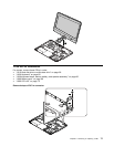
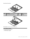
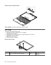
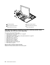
• When you attach the LCD unit to the base cover assembly, rout the cables as shown in the following
illustration.
Chapter 9. Removing or replacing a FRU 85


