


7-5
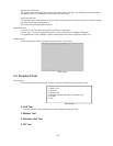
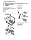
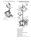
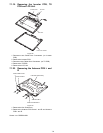
7.1.10. Removing the PAD SW FFC Cover
Figure 9
1. Remove the three Screws<R>, and remove the PAD SW
FFC Cover.
Screws <R>: DFHE5054XA
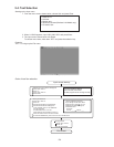
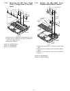
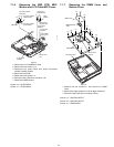
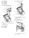
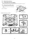
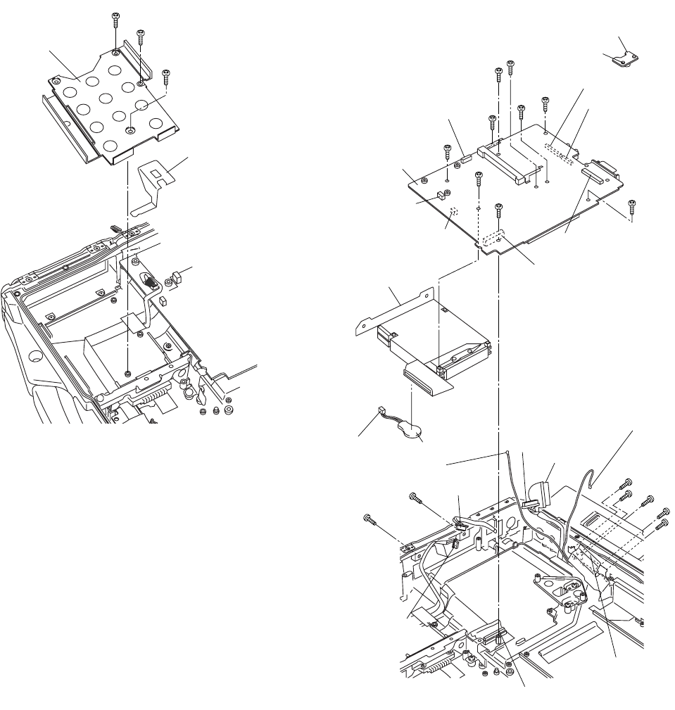
7.1.11. Removing Main PCB, EXT Antenna
PCB, PCMCIA Unit and RTC Battery
Figure 10
1. Remove the two Screws<S>.
2. Remove the two Screws<T-1>.
3. Remove the two Screws<U>.
4. Remove the four Screws<V>.
5. Remove the Screw<W>.
6. Remove the two Screws<X>.
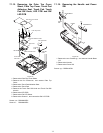
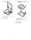
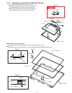
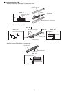
7. Disconnect the six Cables from six Connectors.
(Main PCB: CN1, CN6, CN9, CN10, CN51, CN54)
(EXT Antenna: CN1)
8. Remove the EXT Antenna.
9. Remove the Main PCB.
10. Disconnect the Cable from Connector (CN4).
11. Remove the RTC Battery
12. Remove the four Screws<T-2>, and remove the PCMCIA
Unit.
<R>
<R>
<R>
PAD SW FFC
Cover
Power Cable
Guard
<S>
<S>
<T-1>
<T-2>
<T-2>
<T-2>
<T-2>
<W>
<T-1>
EXT Antenna PCB
Connector
CN1
to Connector
(CN4)
RTC Battery
Connector CN10
(front side)
Connector CN51
(front side)
Connector CN6
(reverse side)
Connector CN9
(reverse side)
Connector CN1
(reverse side)
PCMCIA Unit
to Connector
(CN6)
to Connector
to Connector
(CN9)
to Connector
(CN950)
to Connector
(CN51)
to Connector
(CN54)
to Connector
(CN10)
Connector CN4
(reverse side)
Connector CN54
(reverse side)
Main PCB
<V>
<V>
<X>
<X>
<U>
<U>
<V>
(EXT Antenna CN1)
to Connector
(Main PCB CN1)