


7-28
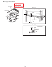
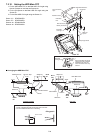
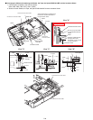
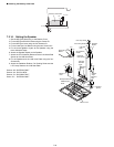
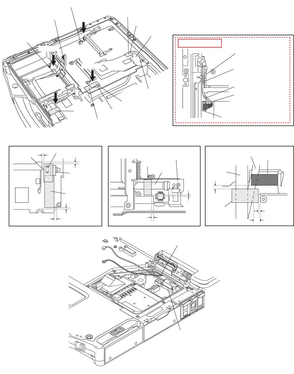
n Arranging the Cables and attaching the Sheets, the Tape, the Space PWB Hold MP and the Insulation Sheet
1. Connect the five Cables to the five Connectors.
(Main PCB: CN6, CN9, CN10, CN51, CN54)
2. Attach the three Sheets, the Tape, the Space PWB Hold MP and the Insulation Sheet.
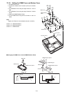
View "A"
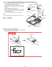
View "B"
View "C"
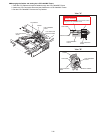
View "D"
View "A"
View "B"View "C"View "D"
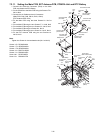
0~1mm
Connect the
Connector CN10.
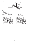
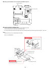
Sheet
Sheet
Sheet
IO FPC
Tape
Insulation Sheet
Insulation Sheet
Space PWB
Hold MP
Tape
Space PWB
Hold MP
IC
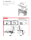
Connect the Connector CN54.
Connect the Connector CN51.
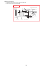
Sheet
Sheet
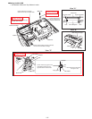
Cable
Cable
Connector CN51
Cable
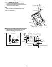
Wireless Module Holder
0~1mm
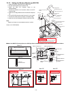
0~1mm
1~2mm
0~1mm
3~4mm
Power SW Cable
CON Spacer
TP PCB
0.5~1.5mm
0~0.5mm
1~2mm
0~1mm
Do not put up the Cable
on the Wireless Module
Holder.
Attach the Sheet in condition that
the IO FPC is slid to the side of
the Connector CN10.
Pass the Cable through
the right side of the
Connector not to put up it
on the Connector.
Safety Working
Connect the Connector CN6.
Connect the Connector CN9.