


7-31
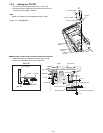
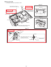
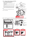
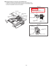
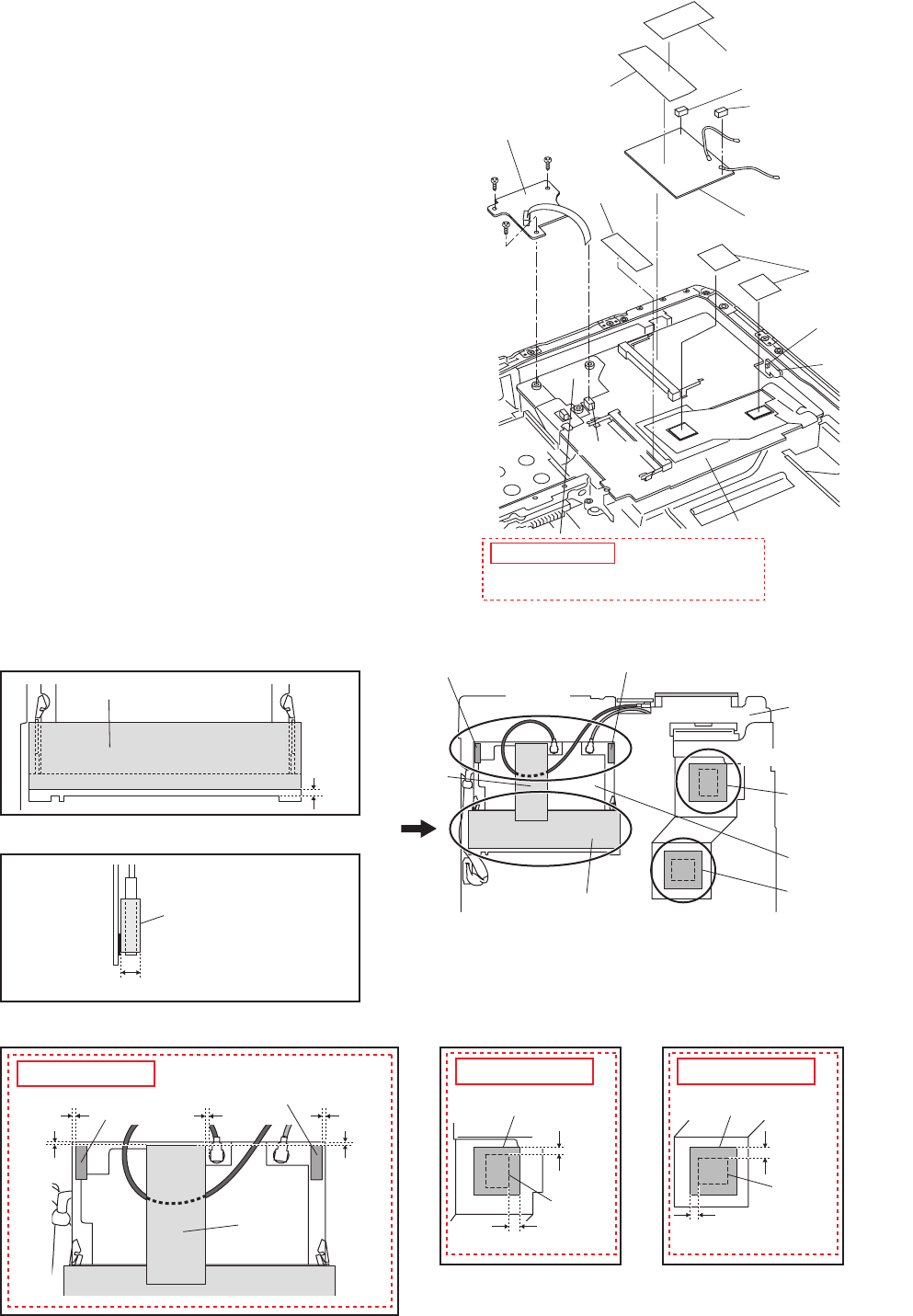
7.2.13. Setting the Wireless Module and SD PCB
1. Attach the Memory Heat Plate to the Main PCB.
2. Set the Wireless Module to the Main PCB.
3.
Attach the MINI PCI Protector Sheet to the
Wireless Module.
4. Connect the Cable to the Connector (CN2) on the EXT
Antenna PCB.
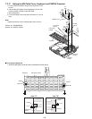
5. Attach the CD Edge Sheet and the two MINI PCI Spacers
U2.
6. Fix the SD PCB using the three Screws<Q>. No1 to No3
7. Connect the Cable to the Connector on the Main PCB.
8.
Attach the two Heat Dissipation Rubbers to the Main PCB.
Note:
Tighten the Screws in the numbered order (No1 to No3).
Screws <Q>: DFHE5025XA
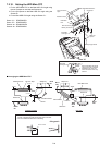
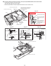
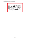
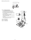
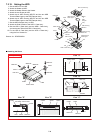
n Attach the MINI PCI Protector Sheet, the CD Edge Sheet, the MINI PCI Spacers U2 and the Heat Dissipation Rubbers
Main PCB
Connector CN2
EXT Antenna
PCB
Connector
SD PCB
<Q>
:No1
<Q>
:No2
<Q>
:No3
to Connector
(CN2)
to Connector
(CN952)
Wireless Module
Memory Heat
Plate
Heat Dissipation
Rubbers
MINI PCI Protector
Sheet
MINI PCI Spacer U2
MINI PCI Spacer U2
CD Edge Sheet
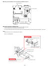
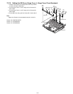
Confirm that the Insulation Sheet is attached
between the SD PCB and the Main PCB.
Safety Working
View "B"
View "D"
View "E"
View "C"
View "A"
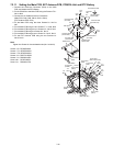
View "C"
View "A"
View "B"
View "D" View "E"
0~0.5mm
0~1mm
0~0.5mm
0~1mm
2~3mm
0~0.5mm
0~0.5mm
4±1mm
1.5~5.5mm
Wireless Module
Heat Dissipation
Rubber
Heat Dissipation
Rubber
Heat Dissipation Rubber
IC
2~3mm
0.5~2.5mm
Heat Dissipation Rubber
IC
Main PCB
MINI PCI Protector
Sheet
MINI PCI Protector Sheet
MINI PCI
Protector Sheet
MINI PCI Spacer U2
MINI PCI
Spacer U2
MINI PCI
Spacer U2
MINI PCI Spacer U2
CD Edge
Sheet
CD Edge
Sheet
Safety Working
Safety Working Safety Working