


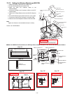
7-27
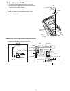
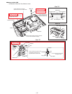
n Setting the Main PCB
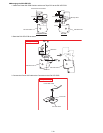
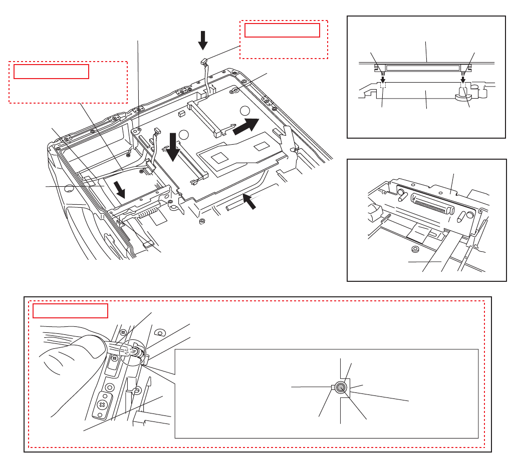
1. Set the Main PCB to the Top Cabinet in order.
View "C"
View "A"
View "B"
View "C"
View "A"
View "B"
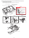
Power SW Cable
Cable
Cable
Main PCB
LAN Cable
LAN Cable
Clamper
Clamper
Confirm that the tying point of the
LAN Cable's Clamper is in the
opposite direction to Main PCB.
Pass the Power SW Cable through
the upper side of Cable.
Confirm that the Pin of the Top
Cabinet of the hole of the Main PCB.
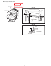
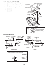
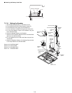
Pull out the LAN Cable
Confirm that the Pin of
the Top Cabinet of the
hole of the Main PCB.
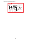
Confirm that the Boss of the Top Cabinet of
the hole of the Batt HDD CN Angle.
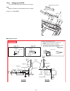
Pass the LAN Cable
through this Slot.
Slot
Tying point
Main PCB
MP CN SpacerHole
Tip of the Screw Tip of the Screw
Hole
Slot
Batt HDD CN Angle
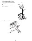
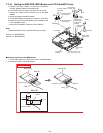
1
2
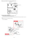
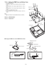
Safety Working
Safety Working
Safety Working