


7-33
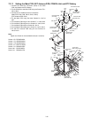
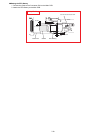
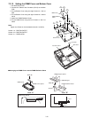
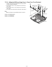
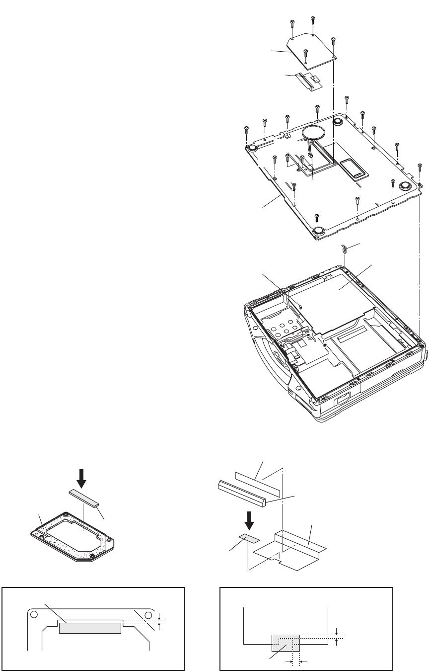
7.2.15. Setting the DIMM Cover and Bottom Cover
1. Set the Bottom Cover.
2. Connect the Cable to the Connector (CN12) on the Main
PCB.
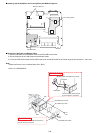
3. Fix the Bottom Cover using the eight Screws<L>. No1 to
No8
4. Fix the Bottom Cover using the eight Screws<K>. No9 to
No16
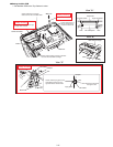
5. Attach the DIMM Radiation Sheet.
6. Fix the DIMM Cover using the four Screws<J>. No17 to
No20
Note:
Tighten the Screws in the numbered order (No1 to No20).
Screws <J>: DRQT26+D4FZLT
Screws <K>: DRQT26+D4FZLT
Screws <L>: DRSB3+8FKL
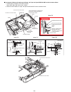
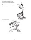
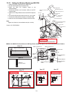
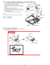
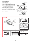
n Arranging the DIMM Cover and the DIMM Radiation Sheet
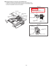
<J>
:No19
<J>
:No20
<J>
:No17
<J>
:No18
<K>
:No9
<K>
:No10
<K>
:No11
<K>
:No12
<K>
:No13
<K>
:No14
DIMM Cover
DIMM Radiation
Sheet
Bottom Cover
Lock Plate
Main PCB
Connector CN12
to Connector
(CN12)
<L>
:No1
<L>
:No2
<L>
:No3
<L>
:No7
<L>
:No8
<L>
:No6
<L>
:No5
<L>
:No4
<K>
:No15
<K>
:No16
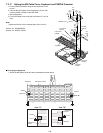
DIMM Cover
DIMM Cover Spacer
DIMM Cover Spacer
DIMM Stopper
DIMM Stopper Spacer
DIMM Radiation Sheet
Sheet
Sheet
View "A"
View "A" View "B"
View "B"
0~2mm
0~2mm
5±2mm