


7-18
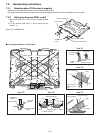
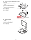
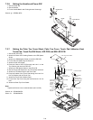
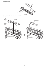
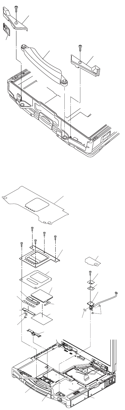
7.2.6. Setting the Handle and Power SW
1. Set the Power SW.
2. Set the Handle.
3. Fix the Handle Base Land R using the two Screws<g>.
Screws <g>: DRSB4+8FKL
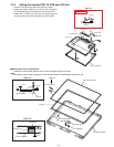
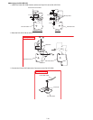
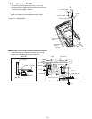
7.2.7. Setting the Palm Top Cover Sheet, Palm Top Cover, Touch Pad Adhesion Seat,
Touch Pad, Touch Pad SW Knob, LED PCB and SW LED PCB
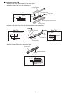
1. Set the SW LED PCB.
2. Attach the Power LED Packing Sheet to the LED Spacer
Sheet.
3. Attach the LEDX6 Spacer Sheet on the SW LED PCB.
4. Fix the SW LED PCB using the Screw<f>.
5. Attach the PW LED Sheet.
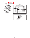
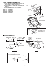
6. Pass the Cable of LED PCB through the hole 1 on the
Top Cabinet, then set the LED PCB.
7. Attach the LED Spacer Sheet on the LED PCB
8. Set the Touch Pad SW Knob In and Touch Pad SW Knob.
9. Attach the TP Bottom Tape to the Touch Pad.
10. Pass the Cables of the Touch Pad through the hole 2 on
the Top Cabinet, set the Touch Pad.
11. Attach the Touch Pad Adhesion Seat.
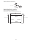
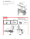
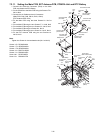
12. Fix the Palm Top Cover using the five Screws<e>. No1 to
No5
13. Attach the Palm Top Cover Sheet.
Note:
Tighten the Screws in the numbered order (No1 to No5).
Screws <e>: DRHM0002ZA
Screw <f>: DRHM0002ZA
Handle
Handle Base L
Handle Base R
<g>
<g>
Power
SW
Palm Top Cover Sheet
<e>
:No2
<e>
:No5
<e>
:No4
<e>
:No3
<f>
Palm Top Cover
Touch Pad
Adhesion Seat
Touch Pad
LED PCB
Cable
Cable
LEDX6
Spacer
Sheet
FCC CN
Stopper
Top Cabinet
Hole 1
Hole 2
Touch Pad
SW Knob
TP Bottom
Tape
<e>
:No1
Touch Pad
SW Knob In
PW LED Sheet
SW LED PCB
Power SW
PCB Cushion
Tape CPU
LED Spacer
Sheet
Power LED
Packing Sheet