


7-21
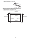
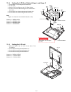
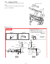
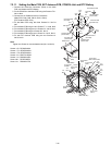
7.2.8. Setting the IO PCB
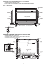
1. Fix the IO PCB using the six Screws<d>. No1 to No6
Note:
Tighten the Screws in the numbered order (No1 to No6).
Screws <d>: DFHE5058ZB
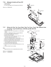
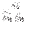
n Arrange the IO FPC
<d>
:No2
<d>
:No3
<d>
:No4
<d>
:No5
<d>
:No6
<d>
:No1
IO PCB
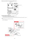
Rear I/O FPC Cover Sheet
View "B"
View "A"
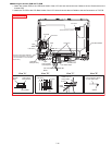
View "A" View "B"
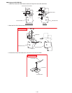
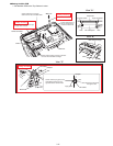
<No good>
2~3mm
R0.5~1.0mm
LID SW
Cushion
IO FPC
R1.5~2.5mm
0±0.3mm
IO FPC
White line
Bend
180
Bend
90
White line
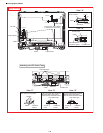
LID SW Cushion
LID SW Cushion
White line
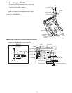
White line
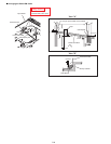
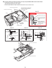
IO FPC
White line
White line
1~1.5mm
Bend
180
Bend
90
Bend
90
Bend
90
Front side
Back side
0~0.5mm
0±0.5mm
0±0.5mm
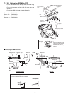
Attention when bending the FPC
1. Inside of bending should be from R0.5mm to
R1mm.
2. Do not mistake the direction of bending.
3. For bending point, it should be within 0.5mm from
the white line unless there is a regulation.
Safety Working