7-9
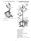
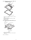
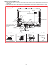
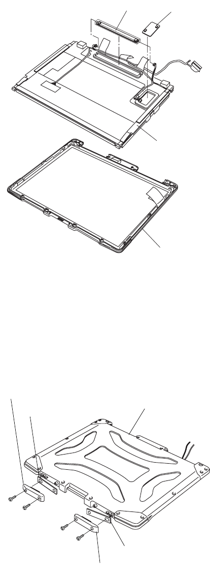
7.1.19. Removing the Inverter PCB, TS
PCB and LCD Unit
Figure 18
1. Disconnect two Cables from Connectors. (on Inverter
PCB)
2. Remove the Inverter PCB.
3. Disconnect two Cables from Connectors. (on TS PCB)
4. Remove the TS PCB.
5. Remove the LCD Unit.
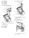
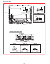
7.1.20. Removing the Antenna PCB L and
R
Figure 19
1. Remove the four Screws<m>.
2. Remove the Antenna PCB Cover L and R and Antenna
PCB L and R.
Screws <m>: DRSB26+8KL
LCD Unit
LCD Front Cabinet
Inverter PCB
TS PCB
<m>
<m>
<m>
<m>
LCD Rear Cabinet Ass’y
Antenna PCB R
Antenna PCB L
Antenna PCB Cover R
Antenna PCB Cover L


