


16
Chapter 3
Functional Details
This chapter contains detailed information on all of the features available from the board, including:
a diagram and explanations of physical board components
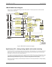
a functional block diagram
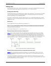
information on how to use the signals generated by the board
diagrams of signals using default or conventional board settings
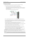
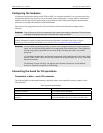
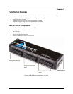
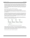
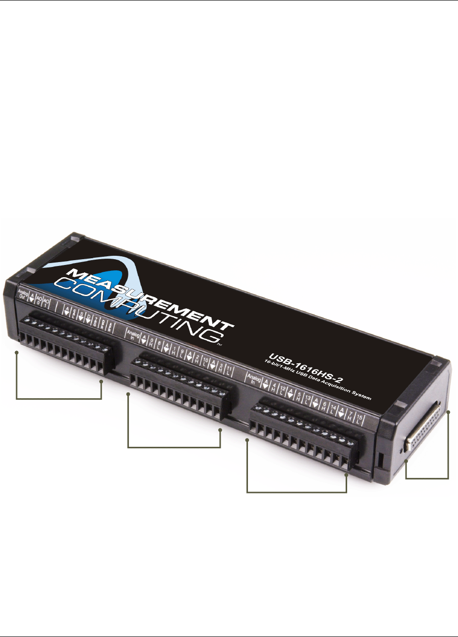
USB-1616HS-2 components
These USB-1616HS-2 components are shown in Figure 4.
Six removable screw terminal blocks
One USB port
One external power connector
One 25-pin expansion connector
Two LED indicators ("Active" and "Power")
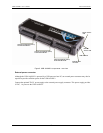
Figure 4. USB-1616HS-2 components – front view
Analog output, calibration,
TTL trigger and pacer signal
Analog input, screw terminal
blocks
Analog input, screw terminal
blocks
DSUB25 expansion
connector