


USB-1616HS-2 User's Guide Functional Details
41
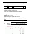
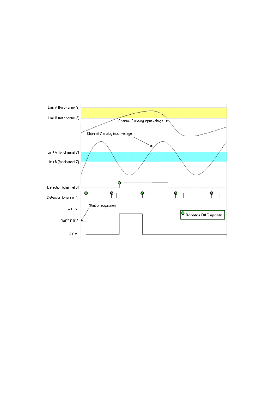
Using multiple inputs to control one DAC output
Update mode: Rising edge, for each of two channels
Criteria used: Inside window, for each of two channels
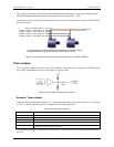
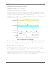
The figure below shows how multiple inputs can update one output. In the following figure the DAC2 analog
output is being updated. Analog input Channel 3 has an inside-the-window setpoint applied. Whenever Channel
3's input goes inside the programmed window, DAC2 will be updated with 3.0 V.
Analog input Channel 7 also has an inside-the-window setpoint applied. Whenever channel 7's input goes inside
the programmed window, DAC2 is updated with - 7.0 V.
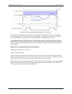
Figure 29. Using two criteria to control an output*
The update on True-only mode was selected, and therefore the updates for DAC2 only occur when the criteria is
met. However, in the above figure we see that there are two setpoints acting on one DAC. We can also see that
the two criteria can be met simultaneously. When both criteria are True at the same time, the DAC2 voltage is
associated with the criteria that has been most recently met.
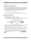
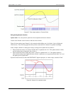
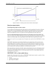
Detecting setpoints on a totalizing counter
In the following figure, Channel 1 is a counter in totalize mode. Two setpoints define a point of change for
Detect 1 as the counter counts upward. The detect output is high when inside the window (greater than Limit B
(the low limit) but less than Limit A (the high limit).
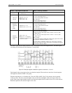
In this case, the Channel 1 setpoint is defined for the 16 lower bits of channel 1's 32-bit value. The
FIRSTPORTC digital output port could be updated on a True condition (the rising edge of the detection signal).
Alternately, one of the DAC output channels, or timer outputs, could be updated with a value.