


USB-1616HS-2 User's Guide Functional Details
33
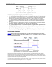
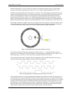
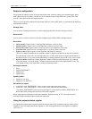
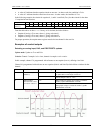
Maximizing encoder accuracy
If there are 512 pulses on A, then the encoder position is accurate to within 360°/512.
You can get even greater accuracy by counting not only rising edges on A but also falling edges on A, giving
position accuracy to 360 degrees/1024.
You get maximum accuracy counting rising and falling edges on A and on B (since B also has 512 pulses.) This
gives a position accuracy of 360°/2048. These different modes are known as X1, X2, and X4.
Connecting the USB-1616HS-2 to an encoder
You can use up to two encoders with each USB-1616HS-2 in your acquisition system. Each A and B signal can
be made as a single-ended connection with respect to common ground.
Differential applications are not supported.
For single-ended applications:
Connect signals A, B, and Z to the counter inputs on the USB-1616HS-2.
Connect each encoder ground to GND.
You can also connect external pull-up resistors to the USB-1616HS-2 counter input terminal blocks by placing
a pull-up resistor between any input channel and the encoder power supply. Choose a pull-up resistor value
based on the encoder's output drive capability and the input impedance of the USB-1616HS-2. Lower values of
pull-up resistors cause less distortion, but also cause the encoder's output driver to pull down with more current.
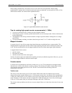
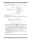
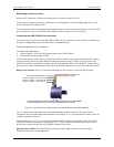
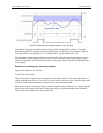
Wiring to one encoder: Figure 21 shows the connections for one encoder to a USB-1616HS-2 module.
Figure 21. Connections from single encoder to screw terminals on the USB-1616HS-2
The "A" signal must be connected to an even-numbered channel and the associated "B" signal must be
connected to the next higher odd-numbered channel. For example, if "A" were connected to counter 0, then "B"
would be connected to counter 1.
Connect each signal (A, B, Z) as a single-ended connection with respect to the common ground. The encoder
needs power from an external power output (typically +5 VDC). Connect the encoder's power input to the
power source and connect the return to the digital common of that source.
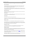
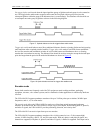
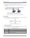
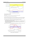
Wiring for two encoders: The following figure illustrates single-ended connections for two encoders.
Differential connections are not applicable.
1
The ground depicted at the left is associated with Digital Common on the USB-1616HS-4.
2
The ground depicted at the right is associated with the external power source.
Ground (to Digital Common
1
)
Counter 0 (CNT0) – To Encoder “A”
Counter 1 (CNT1) – To Encoder “B”
Counter 2 (CNT2) – To Encoder “Z”
To external power
To
g
round
2