


USB-1616HS-2 User's Guide Functional Details
32
debounced from 500 ns to 25.5 ms (total of 16 selections) to eliminate extraneous noise or switch induced
transients. Encoder input signals must be within -5V to +10V and the switching threshold is TTL (1.3V).
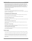
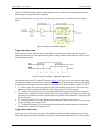
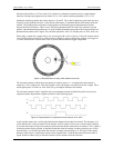
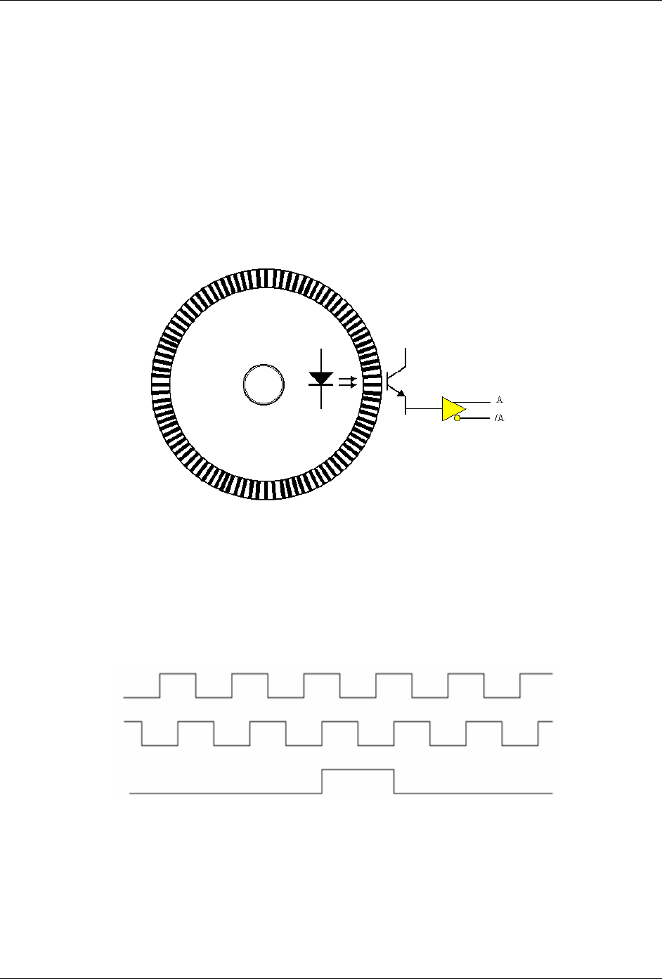
Quadrature encoders generally have three outputs: A, B, and Z. The A and B signals are pulse trains driven by
an optical sensor inside the encoder. As the encoder shaft rotates, a laminated optical shield rotates inside the
encoder. The shield has three concentric circular patterns of alternating opaque and transparent windows
through which an LED shines. There is one LED and one phototransistor for each of the concentric circular
patterns. One phototransistor produces the A signal, another phototransistor produces the B signal and the last
phototransistor produces the Z signal. The concentric pattern for A has 512 window pairs (or 1024, 4096, etc.)
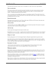
When using a counter for a trigger source, use a pre-trigger with a value of at least 1. Since all counters start at
zero with the initial scan, there is no valid reference in regard to rising or falling edge. Setting a pre-trigger to
1 or more ensures that a valid reference value is present, and that the first trigger is legitimate.
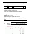
Figure 19. Representation of rotary shaft quadrature encoder
The concentric pattern for B has the same number of window pairs as A—except that the entire pattern is
rotated by 1/4 of a window-pair. Thus the B signal is always 90 degrees out of phase from the A signal. The A
and B signals pulse 512 times (or 1024, 4096, etc.) per complete rotation of the encoder.
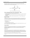
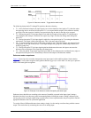
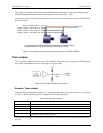
The concentric pattern for the Z signal has only one transparent window and therefore pulses only once per
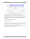
complete rotation. Representative signals are shown in the following figure.
A
B
Z
Figure 20. Representation of quadrature encoder outputs: A, B, and Z
As the encoder rotates, the A (or B) signal indicates the distance the encoder has traveled. The frequency of A
(or B) indicates the velocity of rotation of the encoder. If the Z signal is used to zero a counter (that is clocked
by A) then that counter will give the number of pulses the encoder has rotated from its reference. The Z signal is
a reference marker for the encoder. It should be noted that when the encoder is rotating clockwise (as viewed
from the back), A will lead B and when the encoder is rotating counterclockwise, A will lag B. If the counter
direction control logic is such that the counter counts upward when A leads B and counts downward when A
lags B, then the counter will give direction control as well as distance from the reference.