


USB-1616HS-2 User's Guide Functional Details
30
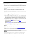
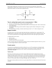
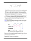
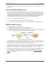
Figure 15. Debounce module – Trigger before stable mode
The following time periods (T1 through T6) pertain to the above drawing.
T1 – In the illustrated example, the input signal is low for the debounce time (equal to T1); therefore when
the input edge arrives at the end of time period T1, it is accepted and the output (of the debounce module)
goes high. Note that a period of stability must precede the edge in order for the edge to be accepted.
T2 – During time period T2, the input signal is not stable for a length of time equal to T1 (the debounce
time setting for this example.) Therefore, the output stays "high" and does not change state during time
period T2.
T3 – During time period T3, the input signal is stable for a time period equal to T1, meeting the debounce
requirement. The output is held at the high state. This is the same state as the input.
T4 – At anytime during time period T4, the input can change state. When this happens, the output will also
change state. At the end of time period T4, the input changes state, going low, and the output follows this
action [by going low].
T5 – During time period T5, the input signal again has disturbances that cause the input to not meet the
debounce time requirement. The output does not change state.
T6 – After time period T6, the input signal has been stable for the debounce time and therefore any edge on
the input after time period T6 is immediately reflected in the output of the debounce module.
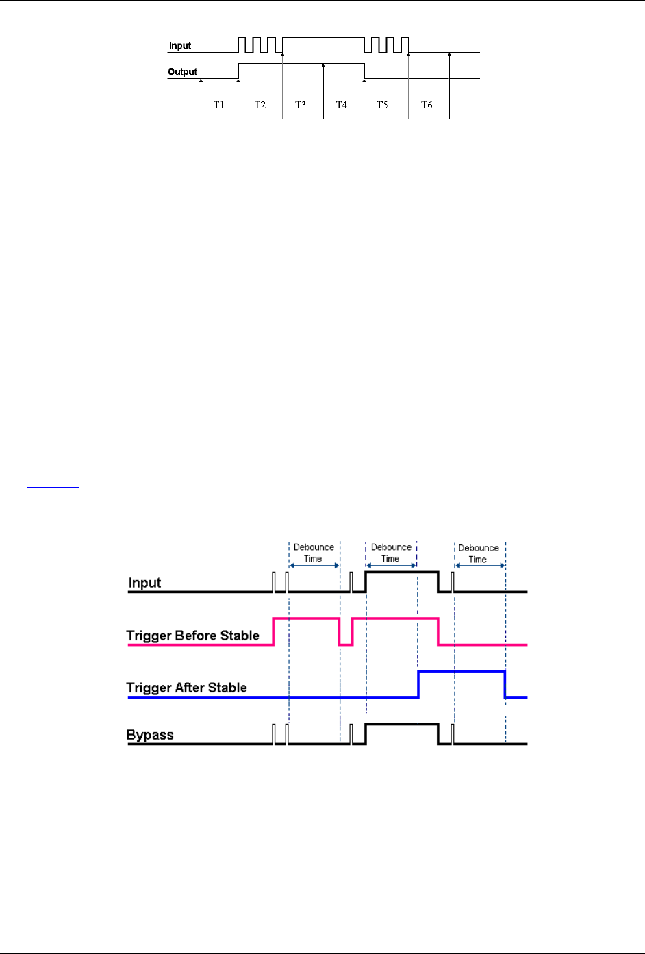
Debounce mode comparisons
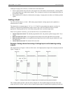
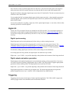
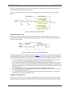
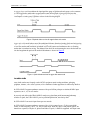
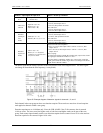
Figure 16
shows how the two modes interpret the same input signal, which exhibits glitches. Notice that the
trigger before stable mode recognizes more glitches than the trigger after stable mode. Use the bypass option to
achieve maximum glitch recognition.
Figure 16. Example of two debounce modes interpreting the same signal
Debounce times should be set according to the amount of instability expected in the input signal. Setting a
debounce time that is too short may result in unwanted glitches clocking the counter. Setting a debounce time
too long may result in an input signal being rejected entirely. Some experimentation may be required to find the
appropriate debounce time for a particular application.
To see the effects of different debounce time settings, simply view the analog waveform along with the counter
output. This can be done by connecting the source to an analog input.