


USB-1616HS-2 User's Guide Functional Details
35
Both timer outputs can also be updated during an acquisition as the result of setpoints applied to analog or
digital inputs.
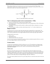
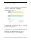
Using multiple USB-1616HS-2s per PC
USB-1616HS-2 features can be replicated up to four times, as up to four devices can be connected to a single
host PC. The serial number on each USB-1616HS-2 distinguishes one from another. You can operate multiple
USB-1616HS-2 boards synchronously. To do this, set up one USB-1616HS-2 with the pacer terminal you want
to use (APR or DPR) configured for output. Set up the USB-1616HS-2 boards you want to synchronize to this
board with the pacer screw terminal you want to use (APR or DPR) configured for input. Wire the pacer
terminal configured for output to each of the pacer input terminals that you want to synchronize.
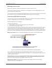
To operate two or more USB-1616HS-2s synchronously:
Use coax (or twisted-pair wire) to connect the output signal to the input(s).
Connect Digital Common of each USB-1616HS-2 to one of the twisted pairs or to the shield of the coax.
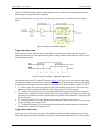
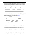
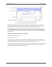
Detection setpoint overview
You can program each as one of the following:
Single point referenced – Above, below, or equal to the defined setpoint.
Window (dual point) referenced – Inside or outside the window.
Window (dual point) referenced, hysteresis mode – Outside the window high forces one output (designated
Output 2; outside the window low-forces another output, designated as Output 1).
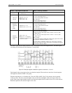
Figure 24. Diagram of detection setpoints
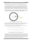
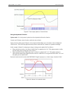
A digital detect signal is used to indicate when a signal condition is True or False—for example, whether or not
the signal has met the defined criteria. The detect signals can be part of the scan group and can be measured as
any other input channel, thus allowing real time data analysis during an acquisition.
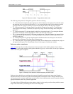
The detection module looks at the 16-bit data being returned on a channel and generates another signal for each
channel with a setpoint applied (Detect1 for Channel 1, Detect2 for Channel 2, and so on). These signals serve
as data markers for each channel's data. It does not matter whether that data is volts, counts, or timing.
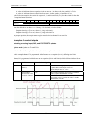
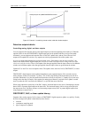
A channel's detect signal shows a rising edge and is True (1) when the channel's data meets the setpoint criteria.
The detect signal shows a falling edge and is False (0) when the channel's data does not meet the setpoint
criteria. The True and False states for each setpoint criteria are explained in the "Using the setpoint status
register
" section on page 37.