


USB-1616HS-2 User's Guide Functional Details
31
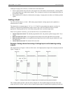
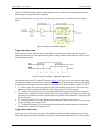
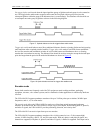
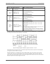
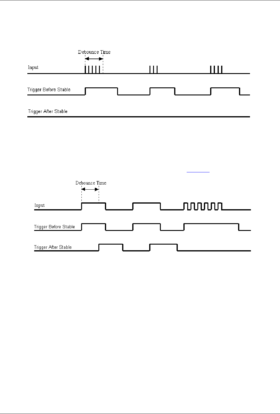
Use trigger before stable mode when the input signal has groups of glitches and each group is to be counted as
one. The trigger before stable mode recognizes and counts the first glitch within a group but rejects the
subsequent glitches within the group if the debounce time is set accordingly. The debounce time should be set
to encompass one entire group of glitches as shown in the following diagram.
Figure 17. Optimal debounce time for trigger before stable mode
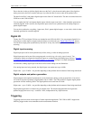
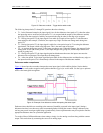
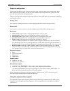
Trigger after stable mode behaves more like a traditional debounce function: rejecting glitches and only passing
state transitions after a required period of stability. Trigger after stable mode is used with electro-mechanical
devices like encoders and mechanical switches to reject switch bounce and disturbances due to a vibrating
encoder that is not otherwise moving. The debounce time should be set short enough to accept the desired input
pulse but longer than the period of the undesired disturbance as shown in Figure 18
.
Figure 18. Optimal debounce time for trigger after stable mode
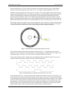
Encoder mode
Rotary shaft encoders are frequently used with CNC equipment, metal-working machines, packaging
equipment, elevators, valve control systems, and in a multitude of other applications in which rotary shafts are
involved.
The USB-1616HS-2 supports quadrature encoders with up to 2 billion pulses per revolution, 20 MHz input
frequencies, and x1, x2, x4 count modes.
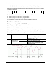
The encoder mode allows the USB-1616HS-2 to make use of data from optical incremental quadrature
encoders. In encoder mode, the USB-1616HS-2 accepts single-ended inputs. When reading phase A, phase B,
and index Z signals, the USB-1616HS-2 provides positioning, direction, and velocity data.
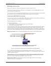
The USB-1616HS-2 can receive input from up to two encoders.
The USB-1616HS-2 supports quadrature encoders with a 16-bit (counter low) or a 32-bit (counter high)
counter, 20 MHz frequency, and X1, X2, and X4 count modes. With only phase A and phase B signals, two
channels are supported; with phase A, phase B, and index Z signals, 1 channel is supported. Each input can be