


USB-1616HS-2 User's Guide Functional Details
40
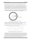
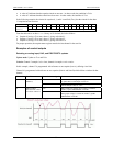
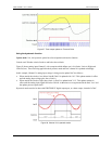
Figure 27. Timer output update on True and False
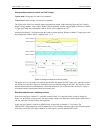
Using the hysteresis function
Update mode: N/A, the hysteresis option has a forced update built into the function
Criteria used: Window criteria for above and below the set limits
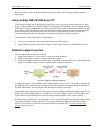
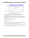
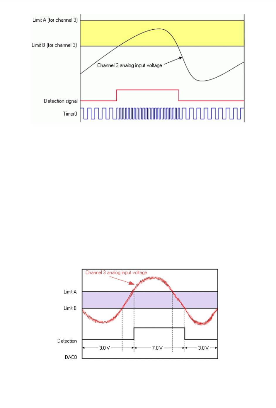
Figure 28 shows analog input Channel 3 with a setpoint which defines two 16-bit limits, Limit A (High) and
Limit B (Low). These are being applied in the hysteresis mode and DAC channel 0 is updated accordingly.
In this example, Channel 3's analog input voltage is being used to update DAC0 as follows:
When outside the window, low (below limit B) DAC0 is updated with 3.0 V. This update remains in effect
until the analog input voltage goes above Limit A.
When outside the window, high (above limit A), DAC0 is updated with 7.0 V. This update remains in
effect until the analog input signal falls below limit B. At that time we are again outside the limit "low" and
the update process repeats itself.
Hysteresis mode can also be done with FIRSTPORTC digital output port, or a timer output, instead of a DAC.
Figure 28. Channel 3 in hysteresis mode