


USB-1616HS-2 User's Guide Specifications
47
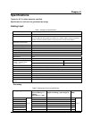
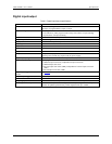
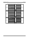
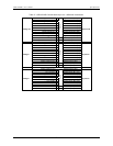
Digital input/output
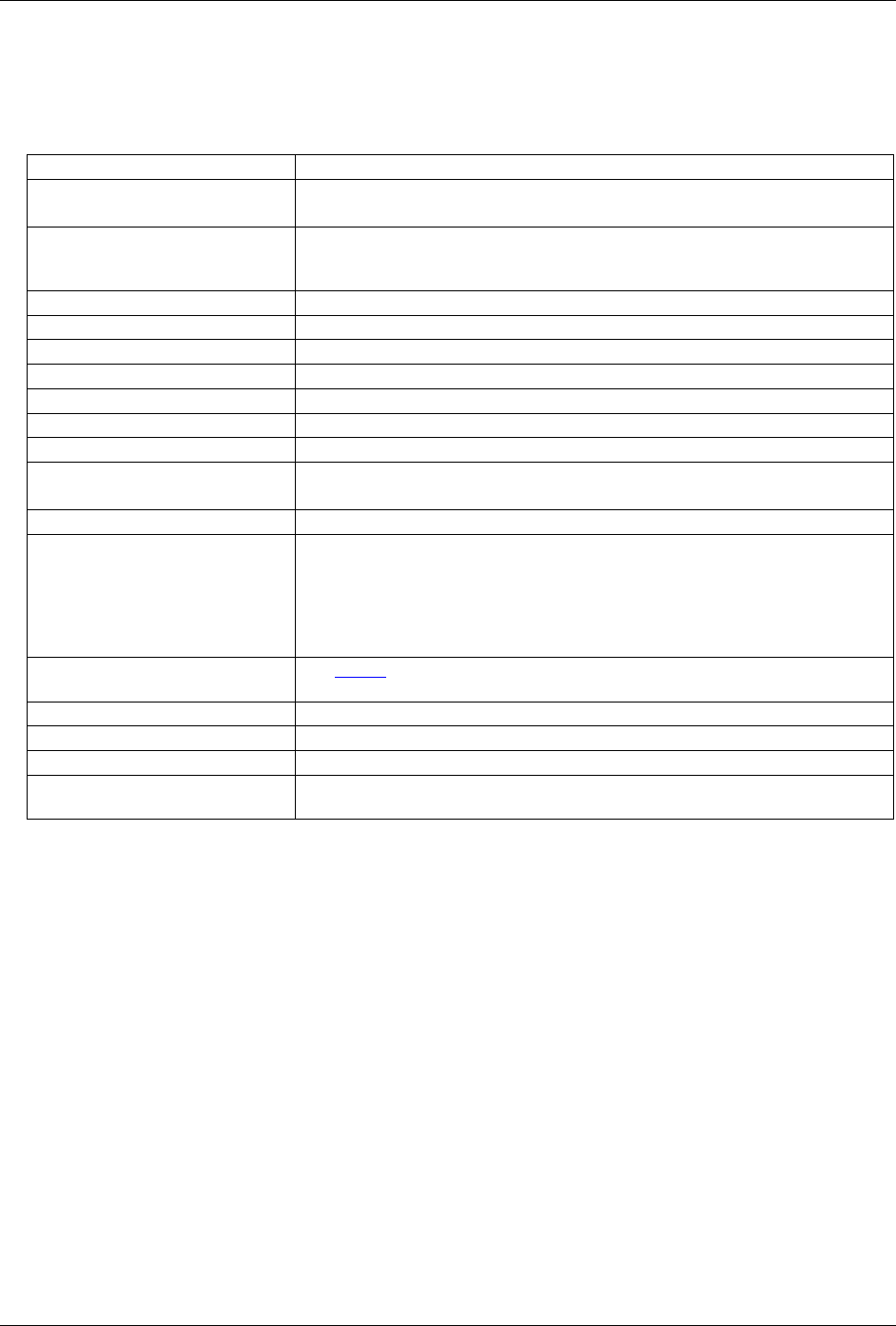
Table 5. Digital input/output specifications
Number of I/O 24
Ports Three banks of eight.
Each port is programmable as input or output
Input scanning modes Two programmable
Asynchronous, under program control at any time relative to input scanning
Synchronous with input scanning
Input characteristics 220 series resistors, 20 pF to common
Logic keeper circuit Holds the logic value to 0 or 1 when there is no external driver
Input protection ±15 kV ESD clamp diodes parallel
Input high +2.0 V to +5.0 V
Input low 0 to 0.8 V
Output high >2.0 V
Output low <0.8 V
Output current Output 1.0 mA per pin
Sourcing more current may require a TR-2U power supply.
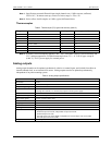
Digital input pacing Onboard input scan clock, external input scan clock (APR)
Digital output pacing Four programmable sources:
Onboard output scan clock, independent of input scan clock
Onboard input scan clock
External output scan clock (DPR), independent of external input scan clock
(APR)
External input scan clock (APR)
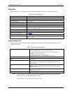
Digital input trigger sources and
modes
See Table 8
Digital output trigger sources Start of input scan
Data transfer DMA
Sampling/update rate 4 MHz maximum (rates up to 12 MHz are sustainable on some platforms)
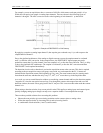
Pattern generation output
Two of the 8-bit ports can be configured for 16-bit pattern generation. The pattern
can also be updated synchronously with an acquisition at up to 4 MHz.