


20
Hardware Installation
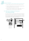
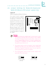
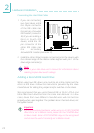
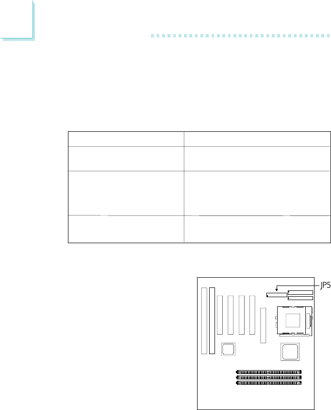
Connecting the Parallel Printer Port
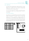
Attach the DB-25 printer port
cable to connector JP5 on the
system board. Make sure the
colored stripe on the ribbon
cable aligns with pin 1 of JP5.
Use a small nutdriver to
mount the cable into a DB-25
cutout in the system chassis. If
your printer port cable is
attached to a card-edge
bracket, connect the cable to
connector JP5 on the system
board and mount the card-edge bracket to the system chassis.
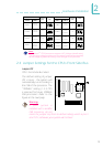
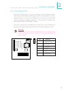
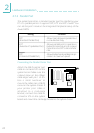
2.7.3 Parallel Port
The system board has a standard printer port for interfacing your
PC to a parallel printer. It supports SPP, ECP and EPP modes. You
can set the ports mode in the Integrated Peripherals setup of the
Award BIOS.
Setting
SPP
(Standard Parallel Port)
ECP
(Extended Capabilities Port)
EPP
(Enhanced Parallel Port)
Function
Allows normal speed operation but
in one direction only.
Allows parallel port to operate in
bidirectional mode and at a speed
faster than the SPPs data transfer
rate.
Allows bidirectional parallel port op-
eration at maximum speed.