


Hardware Installation
21
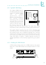
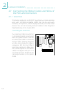
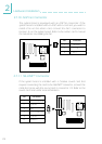
2.7.4 Floppy Disk Controller
The system board is equipped with a shrouded floppy disk header
that supports two standard floppy disk drives. To prevent improper
floppy cable installation, the shrouded floppy disk header has a
keying mechanism. The 34-pin connector on the floppy cable can be
placed into the header only if pin 1 of the connector is aligned with
pin 1 of the header. You may enable or disable this function in the
Integrated Peripherals setup of the Award BIOS.
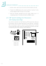
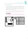
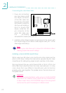
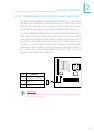
Connecting the Floppy Disk Cable
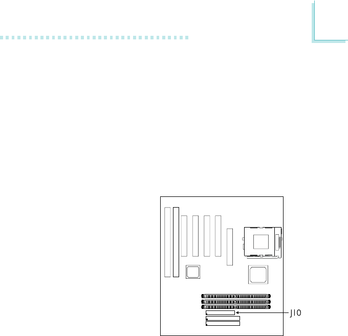
1. Install the 34-pin header
connector into the
shrouded floppy disk
header (J10) on the
system board. The colored
edge of the ribbon should
be aligned with pin 1 of
J10.
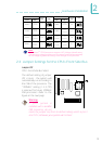
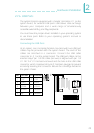
2. Install the other 34-pin
header connector(s) into
the disk drive(s). Align the
colored edge of the daisy
chained ribbon cable with pin 1 of the drive edge connector(s).
The end-most connector should be attached to the drive you
want to designate as Drive A.
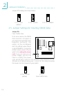
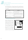
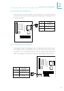
2.7.5 IDE Hard Disk Interface
The system board is equipped with two shrouded PCI IDE headers
that will interface four Enhanced IDE (Integrated Drive Electronics)
hard disk drives. To prevent improper IDE cable installation, each
shrouded PCI IDE header has a keying mechanism. The 40-pin
connector on the IDE cable can be placed into the header only if pin
1 of the connector is aligned with pin 1 of the header.