


30
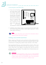
Hardware Installation
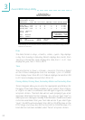
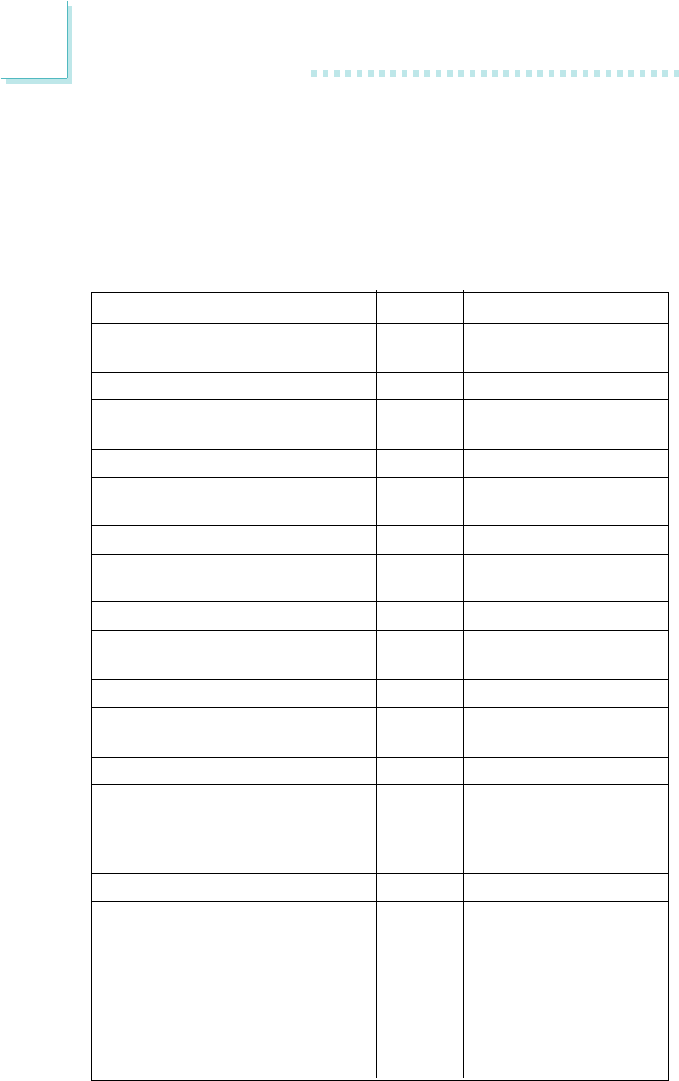
Pin
1
2
3
4
5
6
7
8
9
10
11
12
13
14
15
16
17
18
19
20
21
22
23
24
25
26
27
28
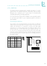
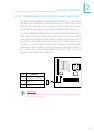
Pin Assignment
ATX-LED
(ATX 5VSB Standby LED)
HD-LED
(Primary/Secondary IDE LED)
G-LED
(Green LED)
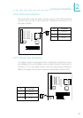
ATX-SW
(ATX power switch)
G-SW
(Green switch)
RESET
(Reset switch)
SPEAKER
(Speaker connector)
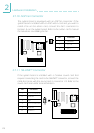
KEYLOCK
(Power/Standby LED and
Keylock connector)
ATX Power
Ground
N. C.
HDD LED Power
HDD
N. C.
Green LED Power
Green
N. C.
PWRBT
Ground
N. C.
SMI
Ground
N. C.
H/W Reset
Ground
N. C.
Speaker Data
N. C.
Ground
Speaker Power
N. C.
LED Power
N.C.
Standby Signal
Keylock
Ground
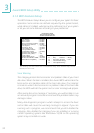
Use pins 24-26 for
the Power/Standby
LED.
KEYLOCK: Power/Standby LED and Keylock Connector
Use pins 24 to 26 to connect to the Power/Standby LED. This LED
will light when the systems power is on and blinks when the system
enters the Suspend mode.
Use pins 27 to 28 to connect to the keyboard lock (located on the
front panel of the system chassis) for locking the keyboard.