124
Sequence Instructions
(1) When the operation result up to the OUT instruction is ON, the coil of the timer
turns on and the timer times up to the setting, and when the timer times out
(timing value
≥ setting), the contact operates as indicated below.
(2) When the operation result up to the OUT instruction turns from ON to OFF, the
timer operates as indicated below.
(3) After a time-out, the contact state of the retentive timer remains unchanged until
the RST instruction is executed.
(4) A negative number (-32768 to -1) cannot be specified for the setting.
(5) If the setting is 0, it is timed as infinity. Hence, the timer does not time out.
(6)
Refer to page 81 for the timing method of the timer.
(1) When the operation result up to the OUT instruction turns from OFF to ON, the
present value (count value) is incremented by 1, and when the counter stops
counting (present value = setting), the contact operates as indicated below.
(2) The counter does not count if the operation result remains ON. (Count inputs
need not be converted into pulses.)
(3) After the counter has stopped counting, the count value and contact state remain
unchanged until the RST instruction is executed.
(4) A negative number (-32768 to -1) cannot be specified for the setting. If the setting
is 0, processing is the same as when the setting is 1.
(5)
Refer to page 83 for the counting method of the counter.
Execution Conditions
Executed every scan independently of the operation result up to the OUT instruction.
OUT(T)
N/O contact Energize
N/C contact Not energize
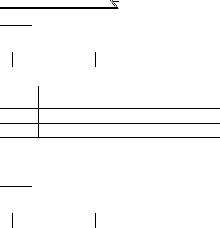
Timer Type
Timer
Coil
Present
Value of
Timer
Before Time-out After Time-out
N/O
contact
N/C
contact
N/O
contact
N/C
contact
100ms timer
OFF 0
Not
energize
Energize
Not
energize
Energize
10ms timer
100ms
retentive timer
OFF Maintained
Not
energize
Energize Energize
Not
energize
OUT(C)
N/O contact Energize
N/C contact Not energize


